


Motor Service
Motor
Page 2
INSPECTING THE MOTOR BRUSHES
1. Make sure the key-switch is in the “OFF”
position, then remove the key.
2. Place the forward-reverse switch in the
center “OFF” position.
3. Set the park brake.
4. Place blocks under the front wheels to
prevent vehicle movement.
5. Disconnect the main positive and
negative cables at the batteries.
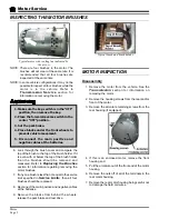
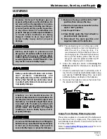
Typical motor with cooling fan indicated by
the arrow
Typical brush and brush holder
NOTE: There are four brushes in the motor. The
brushes will not wear at the same rate. It is
recommended that all four brushes are
inspected at the same time.
NOTE: In some vehicle configurations it may not be
possible to inspect all four brushes while the
motor is in the vehicle. Refer to
Transmission Service
section for
information on removing the motor.
6. Look through the brush cover and compare the
top of the brush to the top of the brush holder. If it
is even with or below the top of the brush holder
then the brushes should be removed and
measured. Refer to
Replacing the Brushes
section for information regarding removing the
motor brushes.
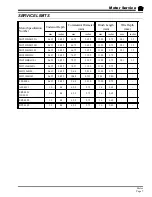
7. If any one brush is less than or equal to the service
limit specified in
Service Limits
, then all four
brushes should be replaced.
8. Reconnect the main positive and negative cables
at the batteries.
9. Remove the blocks from behind the wheels,
release the park brake and test drive.
MOTOR INSPECTION
Disassembly
1. Remove the motor from the vehicle. See the
Transmission
section for information on
removing the motor.
2. Remove the housing screws from the rear and/or
front of the motor.
3. Remove the armature retaining screws from the
rear housing (if equipped).
4. If this is an enclosed motor, remove the front
housing end.
5. Pull the armature out of the front end of the motor
housing.
6. Remove the nuts off of all of the terminals in the
rear motor housing.
7. Remove the rear motor housing being careful not
to damage the field coil wires.
Summary of Contents for ET-015-00
Page 2: ......
Page 14: ...TAYLOR DUNN...
Page 28: ...TAYLOR DUNN...
Page 48: ...Maintenance Service and Repair Steering Page 12 Exploded View of Steering Gear...
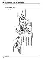
Page 60: ...Maintenance Service and Repair F2 F3 Transmission Page 12 EXPLODED VIEW...
Page 71: ...Maintenance Service and Repair Brakes Page 11 Rear Brake left side shown...
Page 72: ...TAYLOR DUNN...
Page 80: ...TAYLOR DUNN...
Page 90: ...TAYLOR DUNN...
Page 94: ...TAYLOR DUNN...
Page 100: ...TAYLOR DUNN...
Page 114: ...TAYLOR DUNN...
Page 116: ...TAYLOR DUNN...
Page 130: ...Illustrated Parts Parts Page 14 Rear Axle Axle tube 4 5 6 7 3 2 Rear Brakes...
Page 132: ...Illustrated Parts Parts Page 16 Rear Suspension 1 2 3 4 5 6 7 8 9 10 11 12 13 14 Drive Shaft...
Page 134: ...Illustrated Parts Parts Page 18 Motor direct drive Motor Mount direct drive...
Page 142: ...Illustrated Parts Parts Page 26 Instrument Panel dash...
Page 144: ...Illustrated Parts Parts Page 28 Speed Control Panel 1 2 3 4 5 6 7 8 9 10 11 12 4...
Page 152: ...Illustrated Parts Parts Page 36 Charger 2 1 15 12 11 4 3 5 8 10 6 7 9 13 14 16...