


Maintenance, Service, and Repair
Steering
Page 3
If the clamps are positioned so that they
contact other components, it may result in
steering failure and loss of control of the
vehicle causing property damage and/or
severe bodily injury.
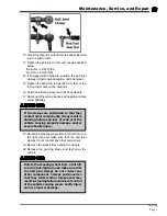
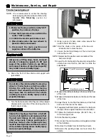
12. Adjust the drag link so that it can be easily inserted
into the pitman arm.
13. Tighten the ball joint or rod end nut as specified
below:
Ball joint - 40-45 ft-lbs.
Rod end - 20-25 ft-lbs.
14. If equipped with ball joints, position the ball joint
clamps in their original location and orientation.
15. Tighten the ball joint clamps (28-32 ft. lbs.) or the
rod end jam nuts on the drag link.
16. Untie the steering wheel and the front wheels.
17. Reconnect the main positive and negative cables
at the batteries.
18. Rotate the steering wheel from a full left turn to a
full right turn and make sure that the ball joint
clamps do not contact any other component.
19. Remove the blocks from behind the wheels.
20. Release the parking brake and test drive the
vehicle.
Rotate the steering wheel from a full left
turn to a full right turn and make sure that
the ball joint clamps do not contact any
other component. Clamps positioned so
that they contact other components may
result in steering failure and loss of control
of the vehicle causing severe bodily injury
and/or property damage.
Summary of Contents for ET-015-00
Page 2: ......
Page 14: ...TAYLOR DUNN...
Page 28: ...TAYLOR DUNN...
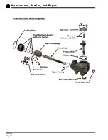
Page 48: ...Maintenance Service and Repair Steering Page 12 Exploded View of Steering Gear...
Page 60: ...Maintenance Service and Repair F2 F3 Transmission Page 12 EXPLODED VIEW...
Page 71: ...Maintenance Service and Repair Brakes Page 11 Rear Brake left side shown...
Page 72: ...TAYLOR DUNN...
Page 80: ...TAYLOR DUNN...
Page 90: ...TAYLOR DUNN...
Page 94: ...TAYLOR DUNN...
Page 100: ...TAYLOR DUNN...
Page 114: ...TAYLOR DUNN...
Page 116: ...TAYLOR DUNN...
Page 130: ...Illustrated Parts Parts Page 14 Rear Axle Axle tube 4 5 6 7 3 2 Rear Brakes...
Page 132: ...Illustrated Parts Parts Page 16 Rear Suspension 1 2 3 4 5 6 7 8 9 10 11 12 13 14 Drive Shaft...
Page 134: ...Illustrated Parts Parts Page 18 Motor direct drive Motor Mount direct drive...
Page 142: ...Illustrated Parts Parts Page 26 Instrument Panel dash...
Page 144: ...Illustrated Parts Parts Page 28 Speed Control Panel 1 2 3 4 5 6 7 8 9 10 11 12 4...
Page 152: ...Illustrated Parts Parts Page 36 Charger 2 1 15 12 11 4 3 5 8 10 6 7 9 13 14 16...