


Maintenance, Service, and Repair
Electrical Troubleshooting
Page 6
Controller Small Signal Input:
During this procedure, voltages will be measured at the controller terminals #1, #2, #6, and #7.
Close the seat interlock switch, turn the key switch ON, select a direction and fully depress the throttle
pedal.
> Terminal #1 should be 12 Volts (nominal).
> Terminal #2 volts should vary between 6 and 11 Volts (nominal) depending on throttle
pedal position.
> In Forward, terminal #6 should be 12 Volts (nominal).
> In Reverse, terminal #7 should be 12 Volts (nominal).
If Terminal #1 failed: Go to Forward/Reverse Switch.
If Terminal #2 failed: Go to Throttle Module.
If Terminal #6 or #7 failed: Go to Forward/Reverse Switch
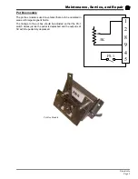
Forward/Reverse Switch:
The Forward/Reverse switch assembly consists of two
micro switches and three diodes. Diodes D2 and D3
provide power to the #1 terminal on the controller. Diode
D4 is a blocking diode to isolate the reverse light circuit
from the control system.
NOTE: For these tests only, “HIGH” = 12 Volts
(nominal).
During this procedure, voltages will be measured at F/R switch Green/Black wire, White/Black wire,
cathode of D4, NO terminal of reverse switch.
Turn the key switch ON, select FORWARD direction and depress the throttle pedal.
> Green/Black wire should be HIGH.
> White/Black wire should be HIGH.
> All others should be LOW.
If Green/Black wire is LOW, go to Throttle Module.
If White/Black wire is LOW, replace the forward switch.
If any other wire or tested terminal is High, then check the reverse switch and wiring for
shorts.
Turn start switch ON, select REVERSE direction and depress the throttle pedal.
> NO terminal on reverse switch should be HIGH.
> D4 Cathode should be HIGH.
> All others should be LOW.
If NO terminal is LOW, replace the reverse switch.
If D4 cathode is LOW, replace the diode.
If any other wire or tested terminal is High, then check the forward switch and wiring for
shorts.
If all above tests are good, then check wiring from F&R switch to the control panel
These test procedures must be
performed in the order they were
written. If the test result is good,
then proceed to the next test or go
to the next section. Failure to do so
may result in incorrect test results.
Summary of Contents for ET-015-00
Page 2: ......
Page 14: ...TAYLOR DUNN...
Page 28: ...TAYLOR DUNN...
Page 48: ...Maintenance Service and Repair Steering Page 12 Exploded View of Steering Gear...
Page 60: ...Maintenance Service and Repair F2 F3 Transmission Page 12 EXPLODED VIEW...
Page 71: ...Maintenance Service and Repair Brakes Page 11 Rear Brake left side shown...
Page 72: ...TAYLOR DUNN...
Page 80: ...TAYLOR DUNN...
Page 90: ...TAYLOR DUNN...
Page 94: ...TAYLOR DUNN...
Page 100: ...TAYLOR DUNN...
Page 114: ...TAYLOR DUNN...
Page 116: ...TAYLOR DUNN...
Page 130: ...Illustrated Parts Parts Page 14 Rear Axle Axle tube 4 5 6 7 3 2 Rear Brakes...
Page 132: ...Illustrated Parts Parts Page 16 Rear Suspension 1 2 3 4 5 6 7 8 9 10 11 12 13 14 Drive Shaft...
Page 134: ...Illustrated Parts Parts Page 18 Motor direct drive Motor Mount direct drive...
Page 142: ...Illustrated Parts Parts Page 26 Instrument Panel dash...
Page 144: ...Illustrated Parts Parts Page 28 Speed Control Panel 1 2 3 4 5 6 7 8 9 10 11 12 4...
Page 152: ...Illustrated Parts Parts Page 36 Charger 2 1 15 12 11 4 3 5 8 10 6 7 9 13 14 16...