
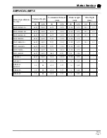


Maintenance, Service, and Repair
Front Axle
Page 2
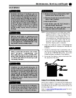
THROTTLE LINKAGE ADJUSTMENTS
Magnetic Module
Throttle Module
The standard magnitic throttle module should
not be used in areas that contain large
magnetic fields. Large magnitic fields may
effect the operation of the module resulting
in unexpected movement of the vehicle.
The throttle pedal is attached directly to the throttle module.
There are no adjustments to the throttle linkage. There are no
serviceable components in the throttle module.
The standard throttle position sensor consists of two micro
switches and a magnetic sensor that detects the position of
the throttle pedal.
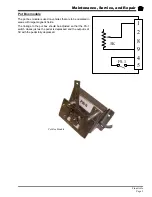
Switch FS-3 is a normally open switch that is held closed by
the throttle pedal return spring. The vehicle will be disabled if
the throttle return spring breaks.
Switch FS-1 closes just as the throttle pedal is depressed.
Depending on the control system in the vehicle, the throttle
position output is obtained from pin #1 (0-5v) or pin #2 (6-
11v).
The start signal output is either a positive or a negative signal
from pin #5. The polarity of the signal depends on the type of
control system in the vehicle and will be the same as the
voltage into pin #4.
Throttle Module Internal Wiring
Throttle Module
FS-1
FS-3
B- Input
6-11 Volt output
36v+ Input
5
9
4
2
7
Summary of Contents for ET-015-00
Page 2: ......
Page 14: ...TAYLOR DUNN...
Page 28: ...TAYLOR DUNN...
Page 48: ...Maintenance Service and Repair Steering Page 12 Exploded View of Steering Gear...
Page 60: ...Maintenance Service and Repair F2 F3 Transmission Page 12 EXPLODED VIEW...
Page 71: ...Maintenance Service and Repair Brakes Page 11 Rear Brake left side shown...
Page 72: ...TAYLOR DUNN...
Page 80: ...TAYLOR DUNN...
Page 90: ...TAYLOR DUNN...
Page 94: ...TAYLOR DUNN...
Page 100: ...TAYLOR DUNN...
Page 114: ...TAYLOR DUNN...
Page 116: ...TAYLOR DUNN...
Page 130: ...Illustrated Parts Parts Page 14 Rear Axle Axle tube 4 5 6 7 3 2 Rear Brakes...
Page 132: ...Illustrated Parts Parts Page 16 Rear Suspension 1 2 3 4 5 6 7 8 9 10 11 12 13 14 Drive Shaft...
Page 134: ...Illustrated Parts Parts Page 18 Motor direct drive Motor Mount direct drive...
Page 142: ...Illustrated Parts Parts Page 26 Instrument Panel dash...
Page 144: ...Illustrated Parts Parts Page 28 Speed Control Panel 1 2 3 4 5 6 7 8 9 10 11 12 4...
Page 152: ...Illustrated Parts Parts Page 36 Charger 2 1 15 12 11 4 3 5 8 10 6 7 9 13 14 16...