


Initial Powerup Tests
3-3
Po
wer Sup
ply T
est
3
6.
Verify that the PS19 DC power switch is turned OFF (downwards).
7.
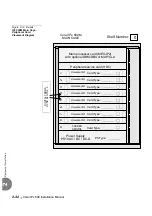
Gently insert the PS19 DC power supply completely into its card slot. Push
against the ejectors until the front panel of the power supply is flush with the
front frame of the card cage. A slight resistance can be felt as the multi-pin
connectors on the power supply meet the mating connectors on the backplane and
engage. Do not force the power supply into the slot. If more than slight resistance
is encountered, remove the power supply and examine the connectors for bent
pins or interfering debris.
8.
Fasten the two screws located at the top and bottom of the unit front panel, thus
securing the card to the cage as well as grounding the unit.
9.
Turn the PS19 DC power switch ON, and verify that the green Power indicator is
lit, while the red Alarm indicator is not lit. If the red alarm indicator illuminates,
see
page 7-13, Troubleshooting (PS19 DC)
.
10.
Turn OFF (downwards) the power switch on the front panel of the PS19 DC.
11.
Repeat
through
for each Coral cage in the system.
12.
Skip to
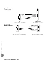
If a minus sign (–) appears in the meter display, the polarity of the 48VDC power to the
cage is reversed. Verify the meter settings and connections. If the meter is properly set
and connected, carefully examine the wiring between the external 48VDC power supply
and/or batteries, determine the location of the polarity reversal, and correct the wiring
error before continuing.
Do not insert or remove the power supply unit from the cage when turned ON.
Sudden power surges could damage system components.
Do not proceed until the screws of the power supply card have been fastened to the
cage. If the screws are not fastened, the power supply unit will not be grounded, and
could be subject to hazardous voltages.
Summary of Contents for Coral IPx 500X
Page 2: ......
Page 4: ......
Page 10: ...vi...
Page 16: ......
Page 22: ......
Page 28: ......
Page 32: ...1 4 Coral IPx 800 Installation Manual Document Description 1 NOTES...
Page 34: ...1 6 Coral IPx 800 Installation Manual Special Symbols Used in this Document 1 NOTES...
Page 40: ......
Page 48: ...2 8 Coral IPx 800 Installation Manual Site Inspection 2 NOTES...
Page 90: ......
Page 116: ...3 26 Coral IPx 800 Installation Manual Shared Service and Peripheral Card Test 3 NOTES...
Page 118: ...3 28 Coral IPx 800 Installation Manual Installation Wrap up 3 NOTES...
Page 120: ......
Page 126: ......
Page 142: ...5 16 Coral IPx 800 Installation Manual Protection Devices 5 NOTES...
Page 150: ...5 24 Coral IPx 800 Installation Manual Terminal Data Communication Ports RS 232E 5 NOTES...
Page 242: ......
Page 278: ...6 38 Coral IPx 800 Installation Manual Cage Description and Installation 6 NOTES...
Page 292: ...6 52 Coral IPx 800 Installation Manual Coral IPx 800X Expansion Cage Description 6 NOTES...
Page 312: ...6 72 Coral IPx 800 Installation Manual System Configuration Options Coral IPx 800 6 NOTES...
Page 314: ......
Page 352: ...7 38 Coral IPx 800 Installation Manual PS19 DC D Power Supply Unit with Duplication 7 NOTES...
Page 368: ......
Page 372: ...8 4 Coral IPx 800 Installation Manual Common Control Cards 8 NOTES...
Page 382: ...8 14 Coral IPx 800 Installation Manual Software Authorization Unit SAU 8 NOTES...
Page 384: ...8 16 Coral IPx 800 Installation Manual MAP 8 NOTES...
Page 386: ...8 18 Coral IPx 800 Installation Manual LIU 8 NOTES...
Page 392: ......
Page 396: ...8 26 Coral IPx 800 Installation Manual HDC Card High Density Control 8 NOTES...
Page 399: ......


