


6-60
Coral IPx 800 Installation Manual
System Co
nfi
gurat
ion
Opti
ons Co
ra
l IPx 8
00
6
0
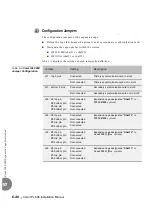
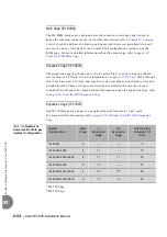
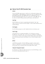
The Coral IPx 800 can be expanded in any one of the following configurations:
Table 6-7 Coral IPx 800
System Expansion
Options
H500 -1 Cable
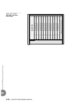
The Coral IPx 800 main cage and its expansion cages maintain a continuous
“conversation”. HDLC and PCM highways, clock and synchronization signals as well
as alarms are constantly exchanged between the cages. All data transfer is carried out
via the H500-1 cable.
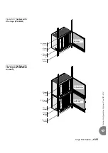
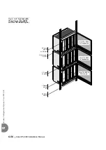
The H500-1 cable is connected from the main cage to the first expansion cage. If an
additional expansion cage is connected, an additional H500-1 cable is connected from
first expansion cage to second expansion cage.
One H500-1 male/female cable, 55" (140 cm) long, is supplied with each IPx 800X cage
or IPx 500X cage.
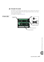
The IPx 500/800 cages include cable connections that allow the expansion cages to be
added.
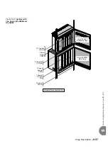
The IPx 800M main cage includes one 50-pin female connection that connects to the
first expansion cage with an H500-1 male/female cable. When there is only main cage
in the system, this connection is not used.
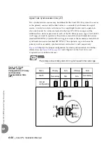
The IPx 800X expansion cage includes two 50-pin cable connections that allow the
expansion cages to be added. The lower connection is female; the top connection is
male. The lower female connection connects the first expansion cage to the second
expansion cage. The top male connection connects either to the female connection on
the main cage or to the female connection on the first expansion cage.
2
Interconnecting Main and Expansion Cages
System Configuration
See Figure
Main Cage
1
st
Expansion
Cage
2
nd
Expansion
Cage
800M
800X
—
800M
800X
800X
800M
500X
—
800M
500X
800X
800M
500X
500X
Summary of Contents for Coral IPx 500X
Page 2: ......
Page 4: ......
Page 10: ...vi...
Page 16: ......
Page 22: ......
Page 28: ......
Page 32: ...1 4 Coral IPx 800 Installation Manual Document Description 1 NOTES...
Page 34: ...1 6 Coral IPx 800 Installation Manual Special Symbols Used in this Document 1 NOTES...
Page 40: ......
Page 48: ...2 8 Coral IPx 800 Installation Manual Site Inspection 2 NOTES...
Page 90: ......
Page 116: ...3 26 Coral IPx 800 Installation Manual Shared Service and Peripheral Card Test 3 NOTES...
Page 118: ...3 28 Coral IPx 800 Installation Manual Installation Wrap up 3 NOTES...
Page 120: ......
Page 126: ......
Page 142: ...5 16 Coral IPx 800 Installation Manual Protection Devices 5 NOTES...
Page 150: ...5 24 Coral IPx 800 Installation Manual Terminal Data Communication Ports RS 232E 5 NOTES...
Page 242: ......
Page 278: ...6 38 Coral IPx 800 Installation Manual Cage Description and Installation 6 NOTES...
Page 292: ...6 52 Coral IPx 800 Installation Manual Coral IPx 800X Expansion Cage Description 6 NOTES...
Page 312: ...6 72 Coral IPx 800 Installation Manual System Configuration Options Coral IPx 800 6 NOTES...
Page 314: ......
Page 352: ...7 38 Coral IPx 800 Installation Manual PS19 DC D Power Supply Unit with Duplication 7 NOTES...
Page 368: ......
Page 372: ...8 4 Coral IPx 800 Installation Manual Common Control Cards 8 NOTES...
Page 382: ...8 14 Coral IPx 800 Installation Manual Software Authorization Unit SAU 8 NOTES...
Page 384: ...8 16 Coral IPx 800 Installation Manual MAP 8 NOTES...
Page 386: ...8 18 Coral IPx 800 Installation Manual LIU 8 NOTES...
Page 392: ......
Page 396: ...8 26 Coral IPx 800 Installation Manual HDC Card High Density Control 8 NOTES...
Page 399: ......