background image

PAGE         

11


Section 2  

  Connecting the System

WINDOW EMITTER 1

WINDOW EMITTER 2

WINDOW EMITTER 3

WINDOW EMITTER 4

WINDOW EMITTER 5

WINDOW EMITTER 6

SOURCE 1 
LOOP  OUT

SOURCE 2 
LOOP  OUT

SOURCE 3 
LOOP  OUT

SOURCE 4 
LOOP  OUT

SOURCE 6 
LOOP  OUT

SOURCE 5 
LOOP  OUT

LINK

ETHERNET

Multi-room Controller

6

1

2

7

8

3

4

10

11

12

14

13

5

9

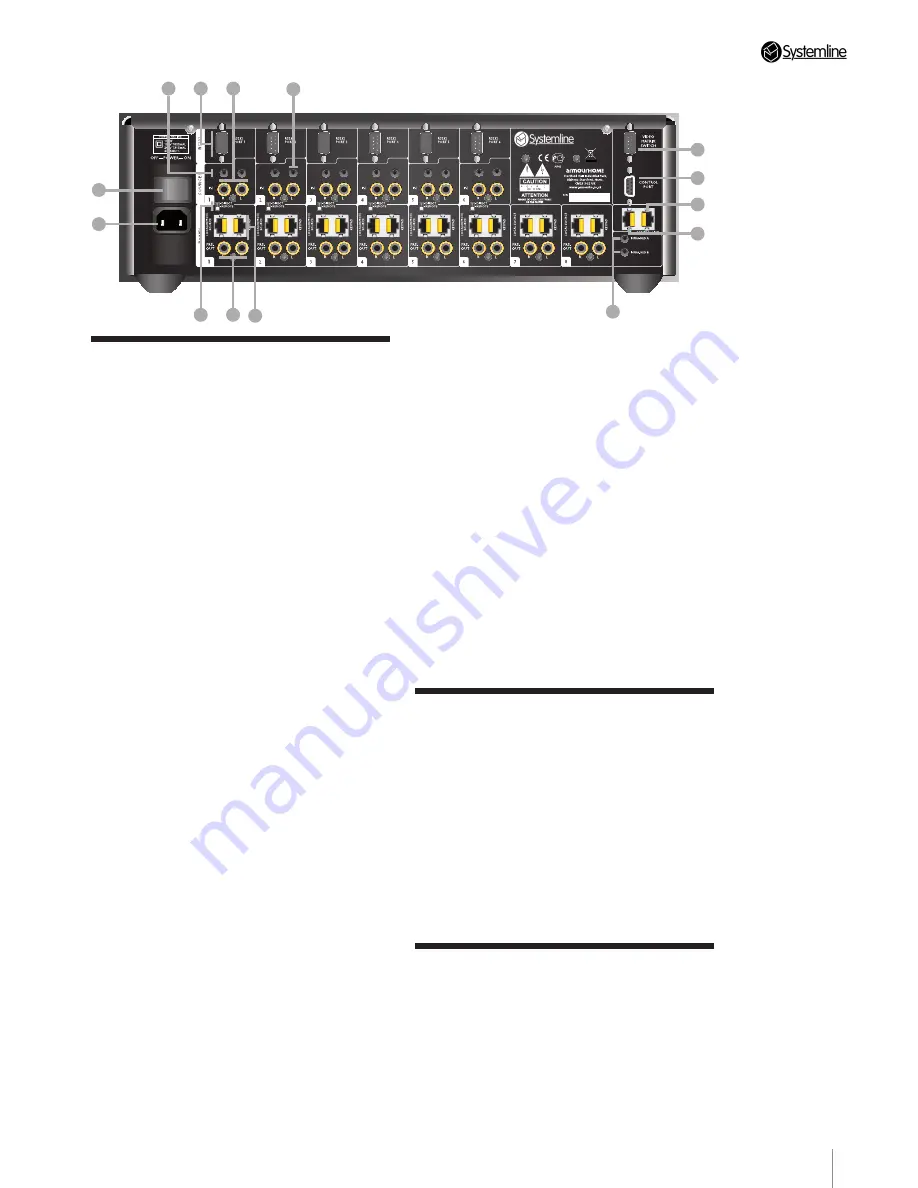
2.8  Rear Panel Connections

1. 

Mains Power

 – ON\OFF switch.

2. 

IEC Mains Inlet

3. 

Direct/Remote Switch

 – when set to 

‘Direct’, the source available to the system is 
that connected to the Phonos.

When set to ‘Remote’, the source located in 

the zone (via CAT5 cable) is available.

Note:


IR is unaffected by this switch.

4. 

Analog audio outputs

 – phono 

connectors from the 8 Zones to Power 

Amplifiers. 

5. 

Keypad

 – RJ45 for connection to the 

keypad in the Zone.

6. 

IR Window Emitter

 – 3.5mm jacks for 

connecting window emmitters to the 6 

sources. An emitter may not be necessary if 

a source is to be controlled via RS232. 

7. 

RS232 ports

 – can be used to control 

audio sources or can be used to control 
other devices such as lighting controllers.

8. 

Analog audio inputs

 – phono connectors 

from the 6 Sources.

9. 

Loop analogue audio output

 – The audio 

loop out allows audio inputs to be connected 
to a second S6.2 controller using a jack 
to phone cable. Only available if using the 
phono audio input sockets.

10. 

IR Output 

– 3.5mm jacks for driving 

Window Emitters. Signal is ‘Global’ IR – all 
zones added together.

11. 

Video Matrix RS232 port 

– for control 

of an Armour 4X8 HDMI matrix or Kramer 

matrix.

12. 

Control RS232 port

 – external control 

systems such as KNX and Lutron can 

control each of the 8 zones using the S6.2 
RS232 control protocol available from www.
systemline.co.uk.

Note:

 Only control of the audio zone is 

possible through this port, no external RS232 
device control such as iPort or Music server 
can be accessed

13. 

Ethernet RJ45 socket

 – This must 

be plugged into a suitable network switch 
or router in order to configure and upload 
software into the S6.2 Controller.

14. 

Link RJ45 socket

 – This is used if two 

S6.2 Controllers are used in one system, a 
standard patch cable is needed for this link.

2.9  Switching on the S6.2 

Controller

Note:

 All wiring should be completed before 

switching on the S6.2 Controller.

When ready, switch on the S6.2 Controller at 
the rear panel.

After a short power-up delay, the S6.2 

Controller will show all zones on standby and 
the standby LED showing red.

2.10 Installation of Sources, 

Lighting Controls and 

Other Units

Refer to the installation and operating 
instructions of the respective equipment for 
other parts of the system.

Summary of Contents for S6.2

Page 1: ...S6 2 Controller S6 2 Controller Installation Guide...

Page 2: ...iquid has been spilled or objects have fallen in to the apparatus the apparatus has been exposed to rain or moisture does not operate normally or has been dropped WARNING Do Not Remove the cover There...

Page 3: ...s Ltd Stortford Hall Industrial Park Dunmow Road Bishops Stortford Hertfordshire CM23 5GZ Web www systemline co uk Terminology This guide uses the following terminology to refer to the components of t...

Page 4: ...nstallation 12 Installing the software on the host computer using the supplied CD ROM 12 3 2 Discovering S6 2 units changing IP address 13 3 3 Setting Touch Screen Keypad wireless junction box address...

Page 5: ...ndow emmitter from the local input wall plate Touch screens can also control other RS232 devices such as lighting and heating control systems These must be a supported device the list of which appears...

Page 6: ...for the S6 2 is updated via the Ethernet connection using a suitable Ethernet switch or router Two units can work on one system to give a sixteen zone system sharing RS232 devices but accessing 6 audi...

Page 7: ...HDMI matrix or the Kramer VP 88ETH component matrix switch 11 Cables as required The following accessories are included with the S6 2 Controller 1 Systemline LRN7 Learning Remote Control 8 SAIC Audio...

Page 8: ...ch setting to 120V Fit a 1 25mA fuse Obtain and fit a suitable 2 pin or 3 pin IEC mains cable power cord 2 3 Wiring Layout See Figure 2 Routing AV sources has not been shown for clarity 2 4 Installati...

Page 9: ...g Mounted Loudspeakers LEFT RIGHT CIM PI DVD Player in Local Zone Wireless Junction Box Power Amplfier ZONE 1 Bookshelf or Floorstanding Loudspeakers Colour Touchscreen Keypad Display HDMI Receiver Sk...

Page 10: ...tronics Technical Support 2 1 3 5 2 4 1 2 7 Front Panel Status Display 1 Zone Condition LEDs shows the current state of each zone RED Standby BLUE System Input RED Local Input 2 IR STATUS IR window em...

Page 11: ...nected to a second S6 2 controller using a jack to phone cable Only available if using the phono audio input sockets 10 IR Output 3 5mm jacks for driving Window Emitters Signal is Global IR all zones...

Page 12: ...llation 3 Click Next to install the SystemNet Configuration Utility into the default location otherwise click browse to choose the directory 4 Click Next to start the installation 5 Click Close when t...

Page 13: ...rk Tab 2 Press the Discover button any S6 2 units discovered will populate by Discovered IP address in the Comms IP address box as shown below S6 2 units come with a DHCP setting for IP address so mus...

Page 14: ...two wireless junction boxes with the same address on the same system even if they are on different S6 2 units Refer to the 16_zone_S6 2 snc file for guidance available from http www armourhe co uk dow...

Page 15: ...have a second S6 2 in the system select this from the Hub drop down menu and continue the process of adding devices You should finish with all devices listed and configured they are shown to be conne...

Page 16: ...box and then ticking the ones you wish to upload 2 Press Upload to load in a complete file including IR 3 Press Upload Without IR to upload a file without the qrc file 3 8 Keypad Configuration Profile...

Page 17: ...the room and speakers e Balance You can offset the stereo signal to the left or right f Fixed Volume This will set the turn on volume to 30 and disable any volume adjustment this is used with AV rece...

Page 18: ...commonly use a Sky Satellite receiver and Systemline Music Server but use different DVD players In this instance the template would simply consist of the saved settings for the Sky and Systemline pro...

Page 19: ...set a different Modular address to avoid accidentally controlling one zone from another 4 Touch Screen Keypad Settings Note S6 2 is designed to work with colour Touch Screen Keypads 4 3 Touch Screen...

Page 20: ...e the contrast can be set such that the screen is unreadable and therefore finding the controls to set it back again is difficult Likewise the Touch Screen Calibration can be set such that the buttons...

Page 21: ......

Page 22: ......

Page 23: ......

Page 24: ...All information is given in good faith The manufacturer accepts no responsibility for errors omissions or incorrect assumptions Armour Home Electronics 2010 ZINS407 ISS3 03 11 10 w w w s y s t e m l...

Reviews: