


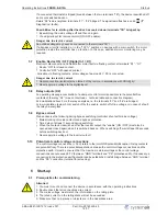


8.2
Connection diagram
N
N
L1
N
L1
PE
Netz
Line
1 ~ 208...277 V 50/60 Hz
L1
U1
U1
U2
U2
K2
E1
GND
TB
TB
D1
D1
GND
A2
D
ig
it
a
l
In
1
A
n
a
lo
g
I
n
1
1
0
V
0
1
Aus / Ein
Off / On
M
1 ~
U1
U2
PE
TB
q
1 ~ Motor
mit eingebauten Thermostatschaltern
with internal thermostats
2
TB
1
Kontaktbelastung
Contact rating
max. AC 250 V 2 A
5
3
UMPO09K13
17.03.2015
FRQ5S-E-6/10A
22
24
21
BU
R
D
BK
0
1
2
3
5
4
1
Line 1 ~ 208...277 V, 50/60 Hz
2
1 ~ Motor with internal thermostats
3
Enable off / on
4
Contact rating max. AC 250 V 2 A
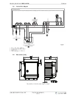
8.3
Dimensions [mm]
Representation of the switch position subject to change!
Operating Instructions
FRQ5S-E-6/10A
Enclosure
L-BAL-E247-GB 1512 Index 001
Part.-No. 00163444-42
16/17