


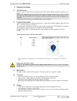


Diagram setting signal and U/f curve (linear)
F
out
[Hz]
F
edge
= F
max
22.05.2013
v_u_f_frq5_sa.vsd
1
2
3
4
5
6
7
8
9
10
Analog In 1
0
45
50
40
35
30
25
20
15
10
5
0...10 V
U
out
100 %
0.5
0
1
2
3
4
5
1
2
3
4
5
0
Analog In:
Speed preset signal by 5-step switch
Fout:
Output frequency
Uout:
Output voltage
Ustart:
Start-up voltage
Foff:
Shutdown Freq.
Fedge:
Edgefrequency
Fmax:
Maximum frequency
Potentiometer for step adaptation
The device operates with the respective possible maximum frequency (
diagram) in every step in
the as-delivered state.
The setting signal (0 - 10 V) for every step and thus the output frequency can be reduced with the
internal potentiometer.
The reduction acts on all steps (1
–
5) in percentage relation. It might therefore be possible to prevents
interference noises caused by resonances at certain frequencies.
Potemtiometer adjustable with a screwdriver
•
Left stop: No reduction, i.e. output frequency e.g. in step 5 = 50 Hz (factory
setting
diagram)
•
Right stop: Maximum reduction 25 %, i.e. output frequency, e.g. in step 5 =
37.5 Hz)
The value of the output frequency can be checked with a suitable measuring
instrument!
Potentiometer for step adaptation
Danger due to electric current
•
It is generally forbidden to carry out work on electrical live parts. Protection class of the device
when open is IP00! It is possible to touch hazardous voltages directly.
•
The device must have been disconnected from the line voltage for at least 3 minutes before
opening!
•
Observe the safety information!
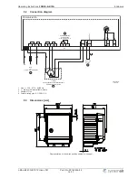
5.6
Motor protection
The motor can be protected by connecting thermostats
“
TB
”
.
When multiple motors are connected, it is essential to ensure that thermostats
“
TB
”
are always
connected in series.
Operating Instructions
FRQ5S-E-6/10A
Electrical installation
L-BAL-E247-GB 1512 Index 001
Part.-No. 00163444-42
11/17