background image

If a connected thermostat is tripped (break between the two terminals 

TB

), the device is switched off 

and is not switched back on. 
Relais 

K2

 is de-energized, terminals 

21

 - 

22

 bridged. The signal lamp 

ashes in code 

|

2

|

 (

Diagnostics / faults).

Possibilities for re-starting after the drive has cooled down (terminals 

TB

 bridged) by: 

By switching the mains voltage off and then on again.

Via a digital input for remote control (ON / OFF enable).

Danger due to electric current                        

An outside voltage may never be connected to the terminals 

TB

If a bypass circuit is installed, or in the 

100 %

 position on devices with a main switch, the motor 

protection inside the controller has no function. In this case, additional motor monitoring may be 
required. 

5.7

Enable, Device ON / OFF (Digital In 1 = D1)

Electronic disconnection and Reset after motor fault via 

oating contact at terminals 

D1

 - 

D1

Device 

ON

 for closed contact. 

Controller 

OFF

 with opened contact.  

Activation via 

oating contacts, a low voltage of approx. 24 V DC is connected.

Danger due to electric current                        

No disconnection (isolation) when turned off by remote, in accordance with VBG4 

§

6)!

Never apply line voltage to the digital input!

5.8

Relay outputs (K2)

An operating message or activation of a damper control motor is possible via the potential-free 
contacts of the relay 

K2

 (max. contact load 

 technical data and connection diagram). 

At a modulation above 5 Hz the relay energizes, i.e. the terminals 

21

 and 

24

 are bridged. 

At low modulation (below 3 Hz), switch off by the enable, switch off of line voltage or in case of a fault, 
the relay de-energizes.

5.9

Bypass circuit

Please observe the following during bypass switching (controller shunt with mains voltage): 

Mutual locking of mains contactor and bypass protection.

Time delay of at least 1 second during switching.

When the contactor is switched off at the inverter output, the 

enable

 (ON / OFF) must also be 

opened and closed again when it is switched back on. When switching off, wait at least 90 seconds 
before switching back on!

Never apply line voltage to the inverter output!

5.10

Potential at control voltage connections

The control voltage connections (< 50 V) relate to the joint GND potential (Exception: Relay contacts 
are potential free). There is a potential separation between the control voltage connections and the 
protective earth. It must be ensured that the maximum external voltage at the control voltage 
connections cannot exceed 50 V (between 

GND

 terminals and 

PE

 protective earth). If necessary, a 

connection to the protective earth potential can be established, install bridge between 

GND

 terminal 

and the 

PE

 connection (terminal for screening).

Start-up

6.1

Prerequisites for commissioning

Attention!

1. You must mount and connect the device in accordance with the operating instructions.
2. Double check that all connections are correct.
3. The mains voltage must match the information on the rating plate.
4. The rated current on the rating plate will not be exceeded.
5. Make sure that no persons or objects are in the hazardous area.

Operating Instructions 

FRQ5S-E-6/10A

 Start-up

L-BAL-E247-GB 1512 Index 001

Part.-No. 00163444-42

12/17

Summary of Contents for FRQ5S-E-10A

Page 1: ...with sine lter for 1 fans Operating Instructions Speed controller with 5 step switch for presetting the fan speed Keep for reference Software version D1628A from Version 11 03 L BAL E247 GB 1512 Index...

Page 2: ...tdoor installation 8 4 4 Installation location for agriculture 9 4 5 Temperature in uences during commissioning 9 5 Electrical installation 9 5 1 Safety precautions 9 5 2 EMC compatible installation 9...

Page 3: ...ical data 14 8 1 1 Max load dependent on ambient temperature and line voltage 15 8 2 Connection diagram 16 8 3 Dimensions mm 16 8 4 Manufacturer reference 17 Operating Instructions FRQ5S E 6 10A L BAL...

Page 4: ...consequence of unauthorized repairs or modi cations 1 4 Copyright These operating instructions contain copyright protected information The operating instructions may be neither completely nor partiall...

Page 5: ...directives rules for the prevention of accidents and the corresponding national as well as regional and in house regulations Personnel to be trained or instructed and apprentices are only permitted to...

Page 6: ...ufacturer s original spare parts wearing parts accessories These parts are specially designed for this device If parts from other sources are used there is no guarantee that they are designed and prod...

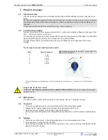
Page 7: ...tep 5 to step 0 is not possible 0 1 2 3 4 5 0 Hz 10 Hz 20 Hz 30 Hz 40 Hz 50 Hz 23 05 2013 v_5_step_icontr_basic_sa vsd The output frequency can be adapted by an internal potentiometer if necessary inv...

Page 8: ...an be easily accessed Depending on the housing model cut off necessary cable inlets respectively to the cable diameter Or alternative use cable inlet for cable glands Metal sheet housings are supplied...

Page 9: ...the device Disregarding this regulation can lead to severe personal injury For metal cable inlets the necessary protective earth connection to the bottom of the housing is made by screws The device ma...

Page 10: ...between two outer conductors all current sensitive fault current circuit breakers must be used EN 50 178 Art 5 2 5 5 Inverter output 5 5 1 Motor connection The motor leads are connected to the termin...

Page 11: ...at certain frequencies Potemtiometer adjustable with a screwdriver Left stop No reduction i e output frequency e g in step 5 50 Hz factory setting diagram Right stop Maximum reduction 25 i e output fr...

Page 12: ...tion below 3 Hz switch off by the enable switch off of line voltage or in case of a fault the relay de energizes 5 9 Bypass circuit Please observe the following during bypass switching controller shun...

Page 13: ...tion above 5 Hz terminals 21 24 bridged De energized at modula tion below 3 Hz 21 22 bridged Temperature management active The device has an active temperature management to protect it from damage due...

Page 14: ...at the output 2 At rated voltage cos 0 8 at the output values for different speci cations on request 3 Max supply side line fuse according to DIN EN 60204 1 classi cation VDE0113 chapter 1 Line voltag...

Page 15: ...pendent on ambient temperature and line voltage The maximum permissible temperature for the rated current at rated voltage is speci ed as rated temperature Since the dissipation of the power loss heat...

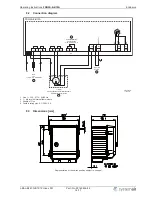
Page 16: ...ernal thermostats 2 TB 1 Kontaktbelastung Contact rating max AC 250 V 2 A 5 3 UMPO09K13 17 03 2015 FRQ5S E 6 10A 22 24 21 BU RD BK 0 1 2 3 5 4 1 Line 1 208 277 V 50 60 Hz 2 1 Motor with internal therm...

Page 17: ...ve any questions concerning the use of our products or plan special uses please contact Systemair Industriev gen 3 73930 Skinnskatteberg Telefon 46 0 222 440 00 Telefax 46 0 222 440 99 mailbox systema...

Reviews: