


FAAST 7100X
INSTALLATION AND MAINTENANCE INSTRUCTIONS
© Pertronic Industries Ltd
6
FAAST XS (7100X) Installation Guide Iss 1.0, 201606
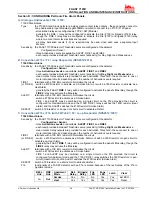
Fault
Isolate
Disable
Low Voltage
Type Description
Active Relay
Low Flow
Fault
Device air flow below the
boundary and delay
programmed by the user.
Fault
Configuration
Configuration of device with
configuration software has
failed
Fault
Device was interrupted with a
power loss during configuration.
Reset to clear this fault and
device reverts to its last good
configuration
Fault
Device is new and has not been
configured
Fault
Device configuration is corrupt
and is unable to operate
Fault
Drift Blue
Fault
Device blue signal has reached
the long term drift limit
Fault
IR Laser Drift
Fault
Device IR Laser signal has
reached the long term drift limit
Fault
Sensor Fault
Device sensor is not working
and requires immediate
replacement
Fault
External
Monitor Fault
External monitor detects open
Fault
Time Fault
Internal Time needs updating
Fault
Aspirator Fault
The fan has stopped working
and requires immediate
attention
Fault
Filter Fault
Device filter is clogged and
requires replacement
Fault
Disable Fault
Device has been put in Disable
mode
Isolate
Isolation Fault
Device has been put in Isolate
mode
Isolate
High Flow
Fault
Device air flow above the
boundary and delay
programmed by the user.
Fault
Low Voltage
Fault
Device Input voltage is low
Fault
Button
Function
Scroll up or down through the LCD menus
Select or enter highlighted item on the LCD
screen
Cancel, Back or Escape from current menu
selection
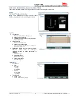
Fault Display:
The FAAST XS user interface displays faults in two ways: using
amber LEDs on the right side of the user interface and on the
LCD screen.
The four Fault LEDs are:
Figure 9: Fault Display
If the General Fault LED is ON, the fault condition is
shown on the LCD Display under the Active Faults menu.
Possible Fault conditions are:
LCD User Interface:
The FAAST XS has an LCD screen to provide detailed
information of the device’s status and configuration. The LCD
typically will be in an idle state where the screen is off. Unless
the LCD sleep timeout, backlight and contrast are configured
through the LCD Settings menu, it will enter a sleep state if a
single screen has remained unchanged for a period of 30
seconds. A single push of any button will wake the screen up
and the home screen will be displayed.
Once the LCD is on, navigate through the menus with the
buttons on the right hand side
Figure 10: LCD Display
The LCD interface supports multiple languages. LCD
Language display is set using PipeIQ or can be changed in the
LCD Settings menu.
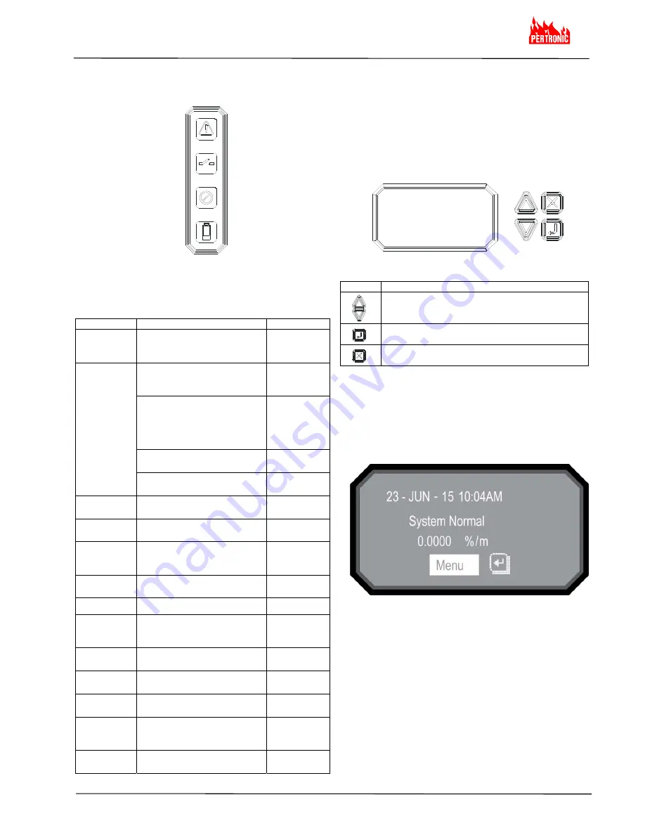
Home Screen:
The Home screen is the default screen, shown when the LCD
is activated. The screen displays the device’s current state
including: Local Address, Date, Time, Current Smoke Level
(percent) and the highest priority state
Figure 11: Home Screen
The menu option is available from the home screen.
Press the Select button to enter the Main Menu screen.
If the device’s Sounder is active, the only selection available is
Silence. Press the Select key to silence the Sounder - then the
menu option will appear.