


FAAST 7100X
INSTALLATION AND MAINTENANCE INSTRUCTIONS
© Pertronic Industries Ltd
5
FAAST XS (7100X) Installation Guide Iss 1.0, 201606
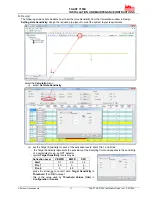
e) User Interface:
The user interface, shown in Figure 5, provides the
following information:
•
Detector status: Normal, Alarm, General Fault,
Isolate Fault, Disable Fault, Voltage Fault
•
Alarm Level: Alert, Fire 1, Fire 2
•
Particulate Level: 1 – 10 relative to Alert
•
Flow
level
•
LCD for device test, service, and monitoring
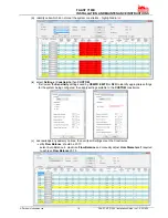
The particulate level display, shown in
Figure 6, consists of ten amber LEDs
that correspond to the current level of
the particulate level detected. The
LEDs illuminate in order from Level 1
to Level 10, starting from the bottom of
the
display and moving up as the
particulate level increases. Each LED
represents
a 10 percent increment in
the particulate level relative to the Alert
level
Display of Particulate Levels occurs
with 7100X detectors, but are not
available with 7200BPI detectors
Figure 6: Particulate Level Display
Figure 5: User Interface Display
Particulate Level Display:
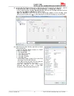
Alarm Level Display:
The alarm level display consists of three red LEDs
whose illumination corresponds to the current alarm
level, shown in Figure 7. These LEDs are located
directly above the particulate level LEDs. They
illuminate sequentially upward as the severity of the
alarm increases. The alarm levels are configured at
default levels when shipped, but may be modified
using the PipeIQ software. Each alarm level controls
a set of Form-C relay contacts. When an alarm level
threshold has been crossed, the corresponding Alarm
LED illuminates and the relay activates after the
Alarm Delay period has elapsed. These alarm
thresholds and associated relay outputs can be
configured for either latching or non-latching
operation. Each Alarm output has a configurable
delay from 0 to 60 seconds
Figure 7: Alarm Level Display
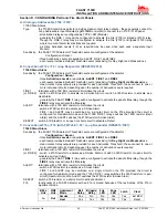
AirFlow Display:
The FAAST XS system uses ultrasonic airflow
sensing and displays the status in
real time on the
user interface. The air flow display consists of 10
green LEDs at
the bottom of the device to display
current flow balance as shown in Figure 8.
The green segments on the air flow pendulum
indicate how close the current
air flow is to a high or
low fault threshold. The default threshold for a fault
condition is + or – 20% from airflow baseline. This
fault threshold is configurable using the PipeIQ
software. During normal operation two adjacent
indicators are green and correspond to the current air
flow entering the detector. When air flow is balanced,
these two indicators will
be centred in the pendulum.
As air flow increases or decreases, the indicators
move to the left in the case of a low flow condition, or
right in the case of
a high flow condition. A flow fault
occurs when the flow boundary threshold is been
exceeded longer than the flow fault delay period. The
fault relay activates when this occurs.
Detailed air flow information can also be read by
accessing the ‘Air Flow’
menu in the device’s LCD
display.
Figure 8: AirFlow Indication