


FAAST 7100X
INSTALLATION AND MAINTENANCE INSTRUCTIONS
© Pertronic Industries Ltd
3
FAAST XS (7100X) Installation Guide Iss 1.0, 201606
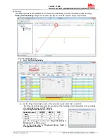
Figure 2: Mounting Slots for Mounting Studs
Figure 3: Power and Alarm Connections
Mount the Detector to the Bracket
Once the mounting plate is attached, the unit is ready to
be mounted onto the plate.
1. before installing the unit onto the bracket, remove the
appropriate conduit cap from the top or bottom-left
side of the unit to match the orientation of the wiring.
2. line up the unit with the three (3) mounting clips and
the mounting studs on the left side.
3. push the unit down onto the mounting clips and
secure it with the supplied washer and nut on at least
one of the two mounting studs protruding through the
mounting slots shown in Figure 2.
Exhaust Pipe
The device should always be exhausted into the space
that it is monitoring. There are some circumstances when
it may be necessary to connect a pipe to the exhaust port
to divert the exhaust away from the location of the unit.
The output ports are tapered the same as the input ports,
to provide fast, easy, push-fit connection of an exhaust
pipe to the unit. Perform the following procedure to
connect the exhaust pipe to the unit.
1. square off and de-burr the end of the exhaust pipe.
Ensure that the pipe is free from any particles that
might interfere with the pipe connection.
2. remove the exhaust plug from the output port being
used (either the top or bottom of the unit).
3. insert the exhaust pipe into the output port, ensuring a
snug fit. DO NOT glue these pipes.
d) Wiring
Before working on the FAAST system, notify all required
authorities that the system will be temporarily out of
service. Make sure all power is removed from the system
before opening the unit. All wiring must be in accordance
with local codes.
Power Cables
Use the power ratings of the unit to determine the
required wire sizes for each connection. Use the power
ratings of the connected products to determine proper
wire size.
Connecting the Air Sampling Pipe
Detailed pipe network information and best practices can
be found in the Pipe Installation Guide, available for
download at systemsensor.com/faast
The input and output ports are designed to accept
standard 25mm OD pipe (one inch). The input and output
ports are tapered to provide fast, easy, push-fit
connection of the sampling pipe to the unit.
Perform the following procedure to connect the air
sampling pipe to the unit.
1. square off and de-burr the end of the sampling air
pipe. Ensure that the pipe is free from any particles
that might interfere with the pipe connection.
2. remove the input plug from the input port being used
(either the top or bottom of the unit).
3. insert the sampling air pipe into the input port,
ensuring a snug fit. DO NOT glue these pipes.
WARNING
WARNING
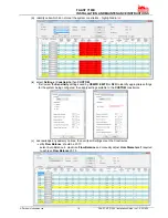
Conduit Usage
If electrical conduit is used for system wiring, terminate
the conduits at the cable entry ports on the top or bottom
of the unit, using the appropriate conduit connectors.
1. run all wiring, both power and alarm,
through the conduit and into the left side of
the unit enclosure, as shown in Figure 3.
2. attach the appropriate wires to the supplied
Euro connector. Follow appropriate local
codes and electrical standards for all
cabling.
3. plug the appropriate connector into the
mating connector on the unit.