technical reference
3
14
Synrad
Firestar i401
operator’s manual
User I/O connections
Input signals
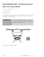
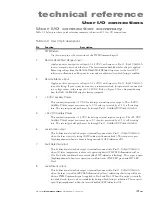
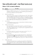
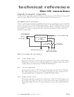
A total of four user inputs allow control of Firestar lasers.
Remote Interlock
,
Shutter Open Request
, and
Remote Reset/Start Request
inputs are optoisolated and bi-directional, allowing for positive or negative
polarity signal inputs. These three signals also share a common return connection,
Input Common
, which
is separate from chassis ground to completely isolate control signals for optimal EMI performance. The
fourth input,
PWM Input
, is optoisolated and has a separate return,
PWM Return
,
to fully isolate PWM
signals from the other three user inputs. Note that throughout this manual, input voltage levels are speci-
fied with respect to their corresponding return line.
Pin 1 PWM Return
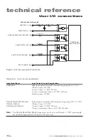
Connect the return side of your PWM Command signal to this pin. Refer to Table 3-4 for input
circuit specifications.
Pin 2 Remote Reset/Start Request
Apply a positive or negative voltage (±5–24 VDC) with respect to Pin 11,
Input Common
, to
disable the laser. The laser remains disabled while voltage is applied to this pin. Removing voltage
from the
Remote Reset/Start Request
pin causes the laser’s
RDY
lamp to illuminate and begins
a five-second countdown after which lasing is enabled. Because all DC power is removed from the
laser’s RF modules when this input is active, no lasing can occur until voltage is removed from
Pin 2. Refer to Table 3-4 for input circuit specifications.
Pin 3 Remote Interlock
Apply a positive or negative voltage (±5–24 VDC) with respect to Pin 11,
Input Common
, to
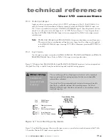
enable lasing. If your system does not use a remote interlock, this pin must be connected to a
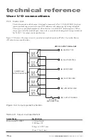
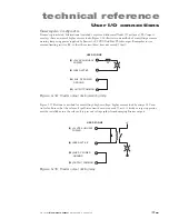
voltage source in the range of ±5–24 VDC. Refer to Figure 3-7 for a diagram showing how the
Remote Interlock
input is factory-jumpered. Because all DC power is removed from the laser’s RF
modules when this input is inactive, no lasing can occur until voltage is applied to Pin 3. Refer to
Table 3-4 for input circuit specifications.
Remote Interlock
faults (
INT
LED illuminates red) are not latched. Re-applying a voltage to Pin
3 enables the
RDY
indicator and lasing is possible after the five-second delay, provided that the
SHT
indicator is also lit.
Use the interlock function to provide maximum operator safety. When the
Remote Interlock
input is opened (voltage source removed), the internal shutter automatically closes to block the
beam path, the
RDY
LED turns Off, the
SHT
LED turns Off (regardless of the state of the
Shutter
Open Request
input), and all DC power is removed from the RF boards.
Pin 9 PWM Input
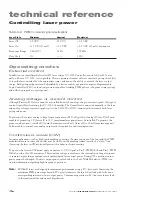
Connect your PWM Command signal (+5 VDC, 5 kHz nominal, 100 kHz max) to Pin 9. This
pulse width modulated Command signal controls laser output so that a duty cycle of 50% cor-
responds to a laser output of approximately one-half rated output power and a duty cycle of 95%
corresponds to approximately full output power. Refer to
Controlling laser power
in this chapter
for further information on laser control signals. Connect the PWM signal source return to Pin 1,
PWM Return
. See Table 3-4 for input circuit specifications.


