getting started
1
17
Synrad
Firestar i401
operator’s manual
Caution
possible
equipment
damage
Do not reverse polarity when connecting the
DC Power Cables
to
your DC power source. Reversed DC polarity may damage the laser’s
internal RF power supply. Carefully follow the directions below to
ensure that
DC Power Cables
are properly connected to the correct
DC output terminals.
Connecting
Note:
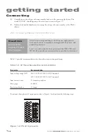
Because AC input connections and requirements vary from facility to facility, custom-
ers must provide the AC power cable or wiring. AC input connections to the PS-401
DC power supply are made using a four-position terminal strip with M4 screw termi-
nals on 13.0 mm centers.
1
Follow your facility’s Lockout/Tagout procedures and verify that input AC voltage to the
DC power supply is physically locked out or disconnected.
2
Connect the ground (earth) wire, typically green, to the input terminal labeled PE.
3
Connect the first three-phase hot wire, typically black, to the input terminal labeled L1.
4
Connect the second three-phase hot wire, typically red, to the input terminal labeled L2.
5
Connect the third hot wire, typically blue, to the input terminal labeled L3.
DC Power Cables
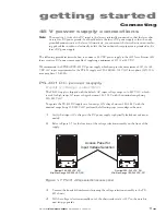
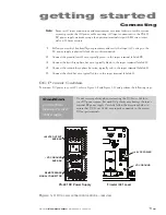
To connect DC power
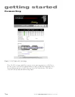
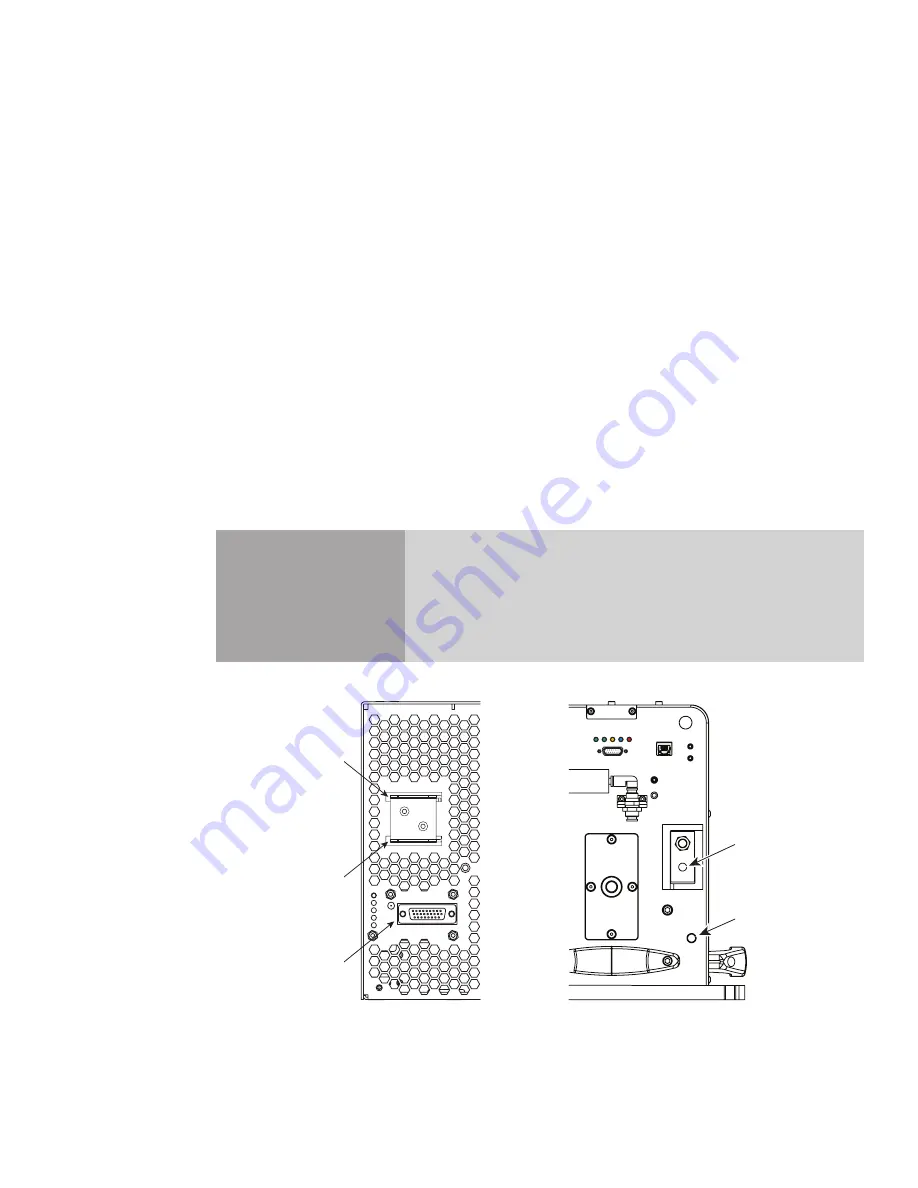
to your i401, refer to Figure 1-9 and Figure 1-10 and perform the following steps:
PS-401 DC Power Supply
Firestar i401 Laser
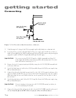
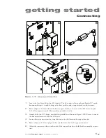
Figure 1-9
DC power connection locations – rear view
SIGNAL
Vadj
T
DC
AC
DC OUTPUT
POS
NEG
+48 VDC OUTPUT
BUS BAR
– VDC GROUND
BUS BAR
REMOTE SENSE
SIGNAL CONNECTOR
– VDC GROUND
+48 VDC POWER


