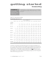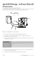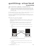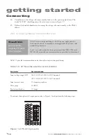
operation
2
3
Synrad
Firestar i401
operator’s manual
Controls and indicators
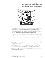
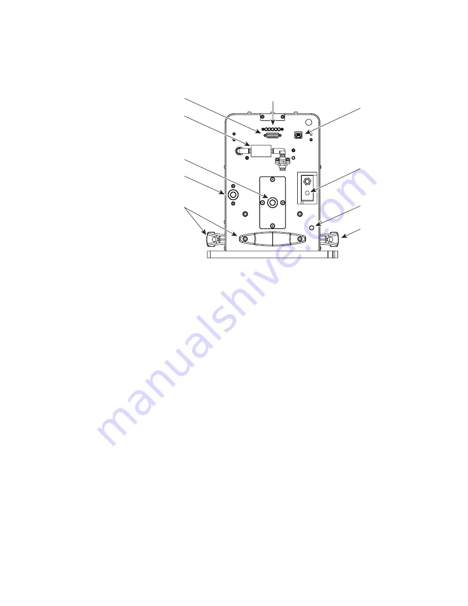
Figure 2-2
Firestar i401 rear panel controls and indicators
5
User I/O
Connector – provides a connection point for auxiliary output power, as well as input and
output signals. Refer to the Technical Reference chapter for pinouts and signal descriptions.
6
Gas Purge
Port/Assembly – provides a low pressure nitrogen (or pure air) connection to prevent dust
and debris from damaging electronic or optical components inside the housing.
7
WATER IN
Port – provides inlet connection for Firestar’s cooling system using straight 1/2-inch fit-
tings. The cooling kit contains 90° tubing adaptors for both 1/2-inch and 12-mm cooling tubing.
8
WATER OUT
Port – provides outlet connection for Firestar’s cooling system using straight 1/2-inch
fittings. The cooling kit contains 90° tubing adaptors for both 1/2-inch and 12-mm cooling tubing.
9
Lifting Handles – allow you to safely lift and move the laser. After laser installation, all three handles
can be removed if additional clearance is necessary.
10
GND
(–) Terminal – M10 × 1.5 threaded stud provides connection point for negative (ground) side
of the 48 VDC power supply.
11
48V POWER
Terminal Block – re48 VDC from the 48 VDC power supply. Fasten the posi-
tive
DC Power Cable
using the supplied M10 × 1.5 bolt at the indicated connection point.
12
Ethernet
Port – provides the connection point for a TCP/IP web-based interface between your com-
puter or network and the i401 laser.
INT
TMP
RDY
WATER
OUT
GAS PURGE
12
4
7
8
6
5
9
10
11
9
WARNING
Do not remove water fittings!
Do not lift or pull on water fittings!
This may cause misalignment or water leaks.
If a water leak is discovered, please contact
Synrad customer service immediately.
USER I/O
ETHERNET
Clean and
Dry Air or
N
2
only
SHT LASE
DC POWER
48 VDC
0 VDC
WATER
IN

