


C-4
SC848 Chassis Manual
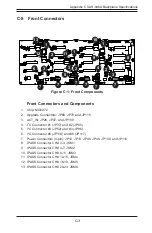
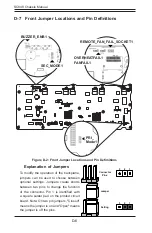
C-6 Front Connector and Pin Definitions
1. MG9072 Chip
The MG9072 is an enclosure management
chip that supports the SES-2 controller and
SES-2 protocols.
2. Upgrade Connectors
The upgrade connectors are designated JP69,
JP78, and JP115 and are used for manufactur-
er's diagnostic purposes only.
3. Activity LED Header
The activity LED header, designated JP26,
JP47 and JP108, is used to indicate the activ-
ity status of each SAS drive. The Activity LED
Header is located on the front panel. For the
Activity LED Header to work properly, connect
using a 10-pin LED cable.
4., 5., 6. I
2
C Connectors
The I
2
C Connectors, designated JP37, JP95,
JP52, JP96, JP116, and JP117, are used to
monitor HDD activity and status. See the table
on the right for pin definitions.
I
2
C Connector
Pin Definitions
(JP37, JP95, JP52, JP96,
JP116, and JP117)
Pin# Definition
1
Data
2
Ground
3
Clock
4
No Connection
Backplane
Main Power
4-Pin Connector
(JP10, JP13, JP46,
JP48, 109 and 110)
Pin# Definition
1
+12V
2 and 3
Ground
4
+5V
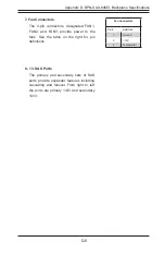
7. Backplane Main Power Connectors
The 4-pin connectors, designated JP10, JP13,
JP46, JP48, JP109, and JP110, provide power
to the backplane. See the table on the right for
pin definitions.
Summary of Contents for SC848 Series
Page 1: ...SC848 CHASSIS SERIES USER S MANUAL 1 0b SUPER SC848A R1K62B SC848E16 R1K62B SC848E26 R1K62B...
Page 32: ...2 20 SC848 Chassis Notes...
Page 38: ...SC848 Chassis Manual 3 6 Notes...
Page 72: ...SC848 Chassis Manual 4 34 Notes...
Page 82: ...SC848 Chassis Manual 5 10 Notes...
Page 86: ...SC848 Chassis Manual A 4 Notes...
Page 88: ...SC848 Chassis Manual B 2 Notes...