48
・
Visually inspect camshaft face and camshaft height for damaged,
and camshaft and bearing for loosening and wearing, replace as
required.
・
Check camshaft for height dimension. If out of the service limit,
replace the camshaft.
・
Check inner diameter of the camshaft hole, if less than the
service limit, replace the camshaft.
・
If the camshaft gear face damaged, please replace the camshaft with new one.
Camshaft wearing cause analyses
:
and to engine performance influence
Poor lubrication will result in camshaft abnormal wearing, such as, oil viscosity low, impurity too much,
and recycling oil little can
’
t let the camshaft surface forming complete oil film to make the camshaft
surface seriously worn in the high speed rubbing stat.
Second, installing precision problem, when the matching clearance of the camshaft journal and camshaft
seat or bearing is out of the service limit, camshaft rotation precision will lower and contacting with the
relative part produce deviation face to make abnormal wearing.
(5) Crankshaft
:
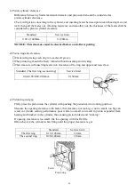
Push the bearing until it
contacts the crankshaft with care not to
damage the crankshaft output end and
timing gear.
・
Check timing gear for engagement
clearance of the chain.
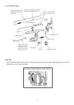
The camshaft, timing chain guide,
tensioner, and crankshaft timing gear
should be sufficiently matched with
chain and contact governor driven gear
of the governor gear.
・
Timing gear will be damaged in gear
worn, gear face peeling off, and gear
teeth broken.
Due to gear wearing, the engagement
clearance is bigger, the noise is bigger.
・
If the timing gear face is damaged,
please replace with new one.
NOTICE: Please replace the gear with a new set to ensure the engaging face completely engage in.
Standard
Service limit
IN lifter
23.98mm
23.730mm
EX lifter
27.88 mm
27.630mm
Standard
Service limit
9.00-9.04mm
9.090mm
Camshaft
Chain guide
Tensioner
Chain
Timing gear
Driven gear
Summary of Contents for EA190V
Page 1: ...EA190V SERVICE MANUAL...
Page 2: ......
Page 8: ...8 II DIMENSION AND TORQUE 2 1 Engine dimension 2 1 1 Appearance dimension...
Page 9: ...9 2 1 2 Installation hole position 2 1 3 P T O dimension figure Engine Mounting Face...
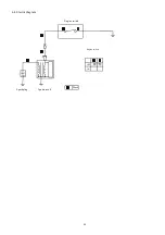
Page 49: ...49 4 4 Electric diagram Engine switch Engine switch Spark plug Ignition coil Black OFF ON...
Page 50: ......
Page 51: ......

