background image

26 

4-2 Preparation of servicing 

4-2-1 Safety precautions 

WARNING


Indicate a possibility of invalid warranty and personal or equipment damage if instructions are 

not followed.   

Please pay special attention to the following: 

1) Strictly set the engine according to the regulated power on the nameplate. Do not overload, overrun 

the engine or run it with low load and at low speed in a long time. 

2) Use regulated brand of gas and fuel. The fuel should be fully deposited and filtrated before use. Keep 

clean the fuel filler, change the oil periodically. 

3) Periodically check the installation, connection and the degree of tightness of the fixed bolt. Tighten it 

if necessary. 

4) Periodically clean the element of the air cleaner, change it when necessary. 
5) The engine is air-cooled, so clean the radiator, wind cover and fan in time in order to make the engine 

cool normally. 

6)  The  operator  should  be  familiar  with  the  working  principle  and  structure  of  the  gasoline  engine, 

knowing how to make an emergent stop and the operation of all controlling parts. Any one without 

training is forbidden to operate the engine. Keep periodical maintenance. Solve problems in time. Do 

not run the engine in spite of malfunction. 

7) Running the engine in a well-ventilated place, keep it at least one meter away from building walls or 

other equipments, keep away from inflammables such as gasoline, matches and so on to avoid 

possibility of fire. 

8) Refuel in a well-ventilated area with the engine stopped, and in places refueling or storing gasoline, 

no smoking and any flames or sparks. 

9) Refuel the fuel tank not too full so as to avoid fuel

s spilling out. If there is spilled fuel around, be sure 

to clean it thoroughly before starting. 

10) Do not run the engine in airtight or ill-ventilated places.   
11) The exhaust muffler is very hot during running the engine even after the engine stops. Never touch it, 

or you may get burns. Transport or store the engine with it cooling down entirely.   

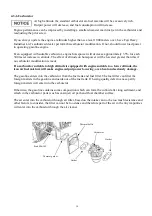
12) Safe warning label: 

Please carefully read warning label before operating. Our company will not assume any responsibility 

for person hurt, or equipment damaged caused by disregarding this warning label. 


4-2-2 Special tools 


Tool name 

Application · note 

Retainer assembler 

Assembler handle 

Inner retainer assembler 

Diamond lap 45

0


Diamond lap 32

0


Flywheel driver 

Bearing extractor 

Assembling ball bearing 

Installing handle and bearing 

Assembling ball bearing and time. 

Rectifying valve seat surface. 

Rectifying valve seat surface. 

Dismounting flywheel 

Dismounting flywheel 

Summary of Contents for EA190V

Page 1: ...EA190V SERVICE MANUAL...

Page 2: ......

Page 3: ...s written permission Safety Messages Your safety and the safety of others are very important We have provided important safety messages in this manual and on the generator Please read these messages c...

Page 4: ...16 3 6 Valve clearance adjustment 17 18 3 7 Governor adjusting 19 3 8 Setting the timing chain 20 IV DISASSEMBLING AND SERVICING 21 4 1 Troubleshooting 21 4 1 1 starting difficult 21 4 1 2 Power lack...

Page 5: ...5 1 PARTS DESCRIPTION 1 1 Part description 1 1 1 Feature Starting lever Air cleaner Fuel tank cap Fuel tank Engine switch Drain plug Spark plug Muffler Oil dipstick...

Page 6: ...pe single cylinder horizontal 4 stroke OHC Displacement 189ml Bore Stroke 68mm 52mm Theoretical Maximum Power 3 72kW 3 600r min Recommended Using Power 3 5 kW 3 400r min Maximum Torque 11 2N m 2 500r...

Page 7: ...0 13 0 28 0 20 0 40 0 150 2 300 1 000 Connecting rod Small end I D Big end I D Big oil clearance Big end side clearance 16 005 16 021 30 000 30 018 0 019 0 049 0 4 0 7 16 090 30 066 0 120 1 100 Crank...

Page 8: ...8 II DIMENSION AND TORQUE 2 1 Engine dimension 2 1 1 Appearance dimension...

Page 9: ...9 2 1 2 Installation hole position 2 1 3 P T O dimension figure Engine Mounting Face...

Page 10: ...78 4 7 Flywheel M14 aluminum flywheel 8 64 4 8 Spark plug M14 1 25 8 8 22 2 M6 12 8 8 9 Cylinder head cover M6 80 8 8 8 2 10 Breath groove covering plate M6 12 8 8 10 2 M6 12 8 8 11 Brake M6 20 8 8 1...

Page 11: ...5 5 6mm screw 7 11 5mm flange bolt 3 6 6 9 6mm screw 7 11 5mm flange bolt 3 6 6 9 6mm flange bolt 10 14 8mm flange bolt 20 26 Bolt and nut 10mm flange bolt 35 45 2 4 Important bolt torque value Torque...

Page 12: ...d inspection at the intervals shown in the Maintenance schedule below Maintenance schedule This items should be serviced by company authorized dealer unless you have the proper tools and mechanically...

Page 13: ...the API service label on the oil container to be sure it includes the letters SE or equivalent SAE10W 30 is recommended for general use Other viscosities shown in the chart may be used when the avera...

Page 14: ...squeeze the foam element in a paper towel to absorb any excess oil 2 Dual Element Type For urethane foam remove it from the paper element and wash it thoroughly with detergent Then dry it before inst...

Page 15: ...tank capacity 1 0L Only use unleaded gasoline and recommend gasoline grade 90 over Unleaded gasoline can reduce gasoline engine carbon deposit and prolong the exhaust system service life Never use co...

Page 16: ...plug on and screw down it with plug wrench compress the plug washer Cover the spark plug cap on NOTICE To avoid cross threading first screw in spark plug by hand then tighten with a spark plug wrench...

Page 17: ...d cover bolt cylinder head cover and gasket in order CAUTION After the cylinder head cover is removed engine oil may flow Be sure to wipe up any flowed oil 2 Lightly pull the starting rope and set the...

Page 18: ...ue 8 2N m Adjusting bolt screw in valve clearance becomes smaller Adjusting bolt screw out valve clearance becomes bigger CAUTION Clearance too big Intake and exhaust valve opening delay will shorten...

Page 19: ...ase have it to the theorized dealer for adjusting If the user has an proper tools and repairing capacity only permit the following operation 1 Start the engine and allow it to warm up to normal operat...

Page 20: ...amshaft sprocket with the mark plate of the opposite end of the timing chain Mark plate Mark plate Timing mark hole The mark plate does not have a camshaft side or crankshaft sprocket side Sprocket fo...

Page 21: ...ear away Electrodes are burn damaged seriously or insulators damaged Replace spark plug Normal high tension line spark Spark plug is in bad conditions Improper electrodes gap Adjust to proper value Hi...

Page 22: ...TROUBLE CAUSE REMEDY Air in fuel line or fuel line clogged Exhaust air or dredge fuel line Main oil flow hole is not adjusted properly Readjust In carburetor needle valve hole and main oil flow hole c...

Page 23: ...y Replace the worn Piston pin and piston pin hole are worn excessively Replace piston or piston pin Tie rod small head is worn excessively Replace tie rod Knocking sound Roller bearing for crankshaft...

Page 24: ...ngine governor to produce speed high Readjust engine governor Crankshaft main bearing burnt out Replace main bearing TROUBLE CAUSE REMEDY Fuel is finished Refill fuel Carburetor is clogged Check fuel...

Page 25: ...d when abnormal combustion occurs Engine fuel is too much Check relative parts such as carburetor Improper fuel brand Replace fuel Engine is overheat Find a cause and eliminate it The other Improper v...

Page 26: ...run the engine in spite of malfunction 7 Running the engine in a well ventilated place keep it at least one meter away from building walls or other equipments keep away from inflammables such as gasol...

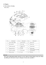
Page 27: ...case 3 Starting rope grip 9 Compression spring 15 Stud M6X80 4 Rope guide assy 10 Washer 16 Stud M6X68 5 Starter coil spring 11 Drive guide 17 Cross recessed pan head screw M5 20 6 Rope coil tray 12 S...

Page 28: ...Fill the fuel into the proper container Remove screw M5 20 fuel tank cover and engine housing Remove the fuel tube fuel strainer and remove the fuel tank Clean the fuel tank and dry it thoroughly Inst...

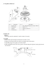
Page 29: ...oil and flywheel with the feeler 3 Adjust Gap between the ignition coil and flywheel 4 Adjust method Loosen the bolt move ignition coil radial along with flywheel to adjust gap and screw down the bolt...

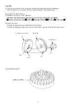
Page 30: ...sassembly 1 Holding the flywheel with a commercially available strap wrench remove the nut M14 2 Disassemble the starter cup and impeller 3 Leave the nut temporarily to prevent the flywheel from dropp...

Page 31: ...art b Set the key in the key groove c Install the flywheel over the crankshaft NOTICE The flywheel may push the key out of its slot check after assembling Flywheel nut torque value 64 4N m aluminum fl...

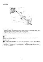
Page 32: ...in water and is seriously rusted to make noise increasing NOTICE Don t clean with iron wire or the muffler material out to lower the muffler performance Don t reuse the muffler gasket WARNING The muff...

Page 33: ...deterioration or damage Replace if necessary Pay attention to connect the beveled end shorter big head end to the air cleaner case while the other end connect to the engine NOTICE Don t wash the foam...

Page 34: ...f a carburetor suitable to high altitude is equipped with engine suitable to a lower altitude the lean air fuel mixture will make engine output power lowering over heat and seriously damage The gasoli...

Page 35: ...recontaminations Don t use the steel wire and other hard material to open the blocked hole to prevent carburetor performance from changing holes diameter Use the gasoline and compression air to clean...

Page 36: ...loat valve seat Normal Worn Reassembly 1 Check the float valve float seat and float spring for wear 2 Clean with compressed air before reassembling 3 Clean with compressed air before reassembling Main...

Page 37: ...lve shaft hole Returning spring hook the left end into the throttle shaft small hole Choke lever hook the left end into the choke shaft hole Governor support Hex Flange nut M6 Support fix bolt Spring...

Page 38: ...ross pattern Especially when tightening all bolts should be tightened gradually and evenly up to specified torque Torque 8 2N m Cylinder head cover Gasket Lock nut Bolt Valve rocker shaft Rocker Exhau...

Page 39: ...ion of a refrigerator for about an hour b Drive the valve guide out of the combustion chamber side using valve guide driver NOTICE Be careful to avoid damaging the cylinder head when driving out the v...

Page 40: ...clearance The vale guide bore detract the valve stem outside diameter to get the clearance between the valve guide and valve stem e If the clearance is over the service limit judge a new guide if it c...

Page 41: ...ny possible burrs at the edges of the seat f After resurfacing seat inspect for even valve seating width Apply colorant to the valve tapered face insert the valve and press it forcefully several times...

Page 42: ...when tightening all bolts should be tightened gradually and evenly up to specified torque Bolt torque 10 2N m Governor gear First check governor gear for worn and damaged then assemble it Governor sp...

Page 43: ...3 Gasket 23 Pin 4 Oil dipstick 14 Flat washer A class 24 Connecting rod 5 Bolt M6 16 15 Governor arm 25 Connecting rod body 6 Lower cover 16 Oil seal 6 11 4 26 Connecting rod cover 7 Deep groove ball...

Page 44: ...nt of the piston ring Stagger the piston ring end gaps 120 apart b Piston pin clip Install by setting front end of the clip in the piston groove holding the other end with long nosed pliers and rotati...

Page 45: ...damaged replace Clean the carbon deposit Clean the deposit round the piston top and cylinder neck before checking first soak the carbon deposit with kerosene and then clean with meter scraper or metal...

Page 46: ...nserting feeler into clearance of the ring and upper and lower face e Piston ring end gap Flatly place the piston into the cylinder with pushing the piston head to working position Measure the opening...

Page 47: ...m NOTICE Place the plastic gauge axially Remove connecting rod and measure with plastic gauge If the clearance exceeds the service limit replace the connecting rod and recheck the clearance 4 Camshaf...

Page 48: ...seat or bearing is out of the service limit camshaft rotation precision will lower and contacting with the relative part produce deviation face to make abnormal wearing 5 Crankshaft Push the bearing u...

Page 49: ...49 4 4 Electric diagram Engine switch Engine switch Spark plug Ignition coil Black OFF ON...

Page 50: ......

Page 51: ......

Page 52: ...ISSUE EMD ES7175 September 2015 Revised...

Reviews: