14
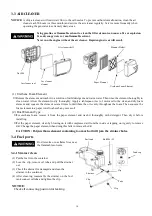
3-3 AIR CLEANER
NOTICE:
A dirty air cleaner will restrict air flow to the carburetor. To prevent carburetor malfunction, clean the air
cleaner each 50 hours (or three month) and service the air cleaner regularly. Service more frequently when
operating the generator in extremely dusty areas.
Using gasoline or flammable solvent to clean the filter element can cause a fire or explosion.
Use only soapy water or nonflammable solvent.
Never run the engine without the air cleaner. Rapid engine wear will result.
(1) Urethane Foam Element
・
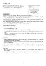
Remove the element and wash it in a solution of mild detergent and warm water. Then rinse the element thoroughly in
clean water. Allow the element to dry thoroughly. Apply a tablespoon (6cc) of motor oil to the clean and dry foam
element and squeeze the element several times to distribute the oil evenly throughout the foam. Then squeeze the
foam element in a paper towel to absorb any excess oil.
(2) Dual Element Type
・
For urethane foam, remove it from the paper element and wash it thoroughly with detergent. Then dry it before
installing.
・
For the paper element, clean by blowing on it with compressed air from the inside or tapping on it gently to remove
dirt. Change the paper element when doing this fails to remove the dirt.
CAUTION: Polyurethane element containing too much oil will jam the strainer holes.
3-4 Fuel parts
Don
’
t smoke or use flame fires near
the flammable solvents.
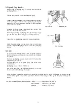
3-4-1 Strainer clean
(1) Put the fuel into the container
(2) Lose the clip, remove oil tube and pull the strainer
out.
(3) Check the strainer for damaged and clean the
strainer in the container.
(4) After cleaning, reassemble the strainer on the fuel
tank connect oil tube and tighten the clip.
NOTICE:
Check all connecting position for leaking.
Furl tank
Tube
Strainer
Clip
Clip
Clip
Bolt M6×25
Tank cap
Air cleaner shell
Air cleaner
element
Nut M6
Air cleaner seat
Urethane Foam Element
Paper Element
Element Holder
Summary of Contents for EA190V
Page 1: ...EA190V SERVICE MANUAL...
Page 2: ......
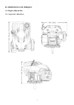
Page 8: ...8 II DIMENSION AND TORQUE 2 1 Engine dimension 2 1 1 Appearance dimension...
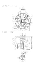
Page 9: ...9 2 1 2 Installation hole position 2 1 3 P T O dimension figure Engine Mounting Face...
Page 49: ...49 4 4 Electric diagram Engine switch Engine switch Spark plug Ignition coil Black OFF ON...
Page 50: ......
Page 51: ......


