


STULZ CyberRow DX Series Installation, Operation & Maintenance Manual
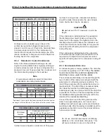
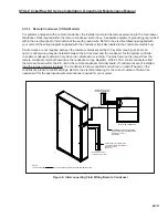
2.10.3 Refrigerant Characteristics
2.10.3.1 Pressure/Temperature Settings
The following table is provided to assist with the
normal settings of the system for R410A refrigerant.
Where applicable, minimum and maximum settings
are given along with normal operating pressures.
R410A Refrigerant Pressure/Temperature Settings
Normal Min. Max.
Sub-cooling °F
10 5 20
Superheat
°F
15 10 20
Design Condensing Temp. @ 95°F Ambient
125
105
140
Suction Pressure (psig)-
130
105
155
Fan Cycling Control- Fan On (psig)-
440
330
480
Fan Speed Control (psig)-
440
-
-
2.10.3.2 Saturated Refrigerant Pressure
The following refrigerant temperature/pressure table
is provided for reference for R410A refrigerant.
Temp.
Pressure
(°F)
(psig)
20
78.4
22
81.9
24
85.5
26
89.2
28
93.1
30
97.0
32
101
34
105
36
109
38
114
40
118
42
123
44
128
46
133
48
137
50
143
55
155
60
170
65
185
70
201
Temp.
Pressure
(°F)
(psig)
75
218
80
236
85
255
90
274
95
295
100
318
105
341
110
365
115
391
120
418
125
446
130
477
135
508
140
541
R410A Refrigerant Pressures
2.11 Settings and Adjustments
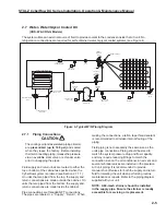
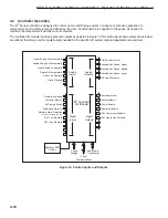
2.11.1 Water-Water/Glycol Circuit
Condensing temperature is maintained by liquid
fl owing through a regulating valve and then into the
condenser. The regulating valve opens to increase
the liquid fl ow as the refrigerant pressure rises
(or closes as the refrigerant pressure falls). The
system controller monitors a signal from a pressure
transducer to determine how far to open the valve.
The controller automatically changes the control
valve position to maintain head pressure based on
the difference between the setpoint value and the
actual measured value. The controller transmits a
proportional 0 to 10 VDC signal to the regulating
valve with 10 VDC corresponding to the valve
opening 100%.
The system controller is factory set for the correct
condensing pressure however, it can be adjusted
to increase or decrease the pressure. Adjustment
is made by entering the Factory menu in the
E²
controller. Contact STULZ Product Support for a
password to enter the Factory menu and for technical
assistance if adjustment is necessary.
Adjustments should be made in small increments.
Adequate time must be allowed between adjustments
for the valve to fully respond to the control signal and
for the changes in system operation to be observed.
2.11.2 Low/High Pressure Limit Switch
Air conditioning systems utilizing DX refrigerant are
equipped with hermetically sealed high-pressure and
low-pressure switches. These switches are pre-set by
the manufacturer and cannot be adjusted. The high-
pressure switch opens at 630 psig and has a manual
reset. The low-pressure switch opens at 65 psig (± 10)
and closes at 105 psig (± 10) and has an automatic
reset.
2.11.3 Thermal Expansion Valve
An electronically controlled expansion valve (EEV)
maintains constant superheat of the refrigerant vapor
at the outlet of the evaporator by metering the fl ow
of refrigerant into the evaporator. Superheat is the
difference between the refrigerant vapor temperature
and its saturation temperature at a given suction
pressure. By controlling superheat, the EEV keeps
nearly the entire evaporator surface active while
preventing liquid refrigerant from returning to the
2-18
Summary of Contents for CyberRow DX CRS-042-G
Page 94: ......


