


STULZ CyberRow DX Series Installation, Operation & Maintenance Manual
4-17
(Continued from previous page)
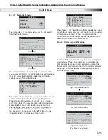
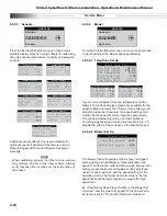
4.5.2.12 Group Information Menu Screens
The Group Information menu screens only appear if the controller is set
up to operate multiple A/C unit work group. See Section 4.6.2.8 for a more
detailed description of these screens.
Group T/H Sensors
Avg 000.0 °F
000.0 %
Min 000.0 °F
000.0 %
Max 000.0 °F
000.0 %
Min Temp 0
Min Hum 0
Max Temp 0
Max Hum 0
Net T/H Sensors
00.0°F
00.0%rh
T/H Sensor Value Local
Unit 0 of 0 Lead: 1
Group Alarms
1-8:
000
9-16:
000
17-24:
000
25-32:
000
33-40:
000
41-48:
000
49-56:
000
Press ( ) or ( ) Key
Information Menu
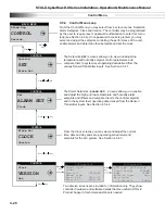
4.5.2.10 EHGB Status
Displays the current operating position of the electronic hot gas bypass valve.
The current suction temperature appears below. The bar gauge next to the valve
icon provides a visual representation of the output signal controlling the valve
position.
Press ( ) or ( ) Key
EHGB Status
Pos: 50.0%
Temp: 30.0°F
4.5.2.13 Software Version/Date
Displays the type of A/C system the controller is confi gured for (W/G, AR), the
STULZ software version and it's release date.
1 W/G-12" CyberRow
E2C V: 1.2
09/20/12
STULZ
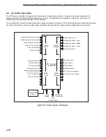
Fan Status
80.0%
Var frm Avg 000.0°
F
80.0%
Var frm Avg 000.0°
F
80.0%
Var frm Avg 000.0°
F
The message "
Var from Avg
" or "
Temp Prop
" appears indicating the
speed control confi guration (see Section 4.4.4.1). The message in the fi eld is
replaced with "
Dehum
" when the system is in the dehumidifi cation mode. In the
dehumidifi cation mode the animated icons are always inked together indicating
the three fans are being controlled to the same (dehumidifi cation) fan speed
setting.
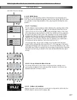
4.5.2.11 Fan
Status
The Fan Status screen displays symbols indicating the operating status of the
upper, middle and lower fans. The symbols are animated when the fans are
running. If a fan is not running, the
symbol will appear instead. The value
of the proportional output signal (0 to 100%) that controls each fan appears in
the fi eld to the right of each symbol. The animated icons are linked together
indicating the three fans are being controlled to the same fan speed setting
(default). The controller also displays the temperature value for the sensor
from each fan zone. The fans may be linked or unlinked in any combination
for individual zone temperature control (see Section 4.5.4.1).
Fan Status
80.0%
Var frm Avg 000.0°
F
80.0%
Var frm Avg 000.0°
F
80.0%
Var frm Avg 000.0°
F
Or,
Summary of Contents for CyberRow DX CRS-042-G
Page 94: ......


