


STULZ CyberRow DX Series Installation, Operation & Maintenance Manual
units are all in the rotation cycle so even a standby unit
will be cycled into active duty on a scheduled basis.
A/C units in the group may have their duty assignments
locked so they do not join the rotation cycle (and cannot
take the lead). In this case the message "
No_Rot
"
appears after the duty assignment displayed in the main
screen.
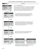
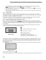
01/01/09 00:00:00
00.0°F
00%rh
Dp 00.0°F
Unit On
ACTIVE_No_Rot
An Active_No_Rot unit is always On therefore, it will not
rotate out. An Active_No_Rot unit will still be able to
take the role as lead controller during a rotation. Units
designated as "Out of Service" do not rotate nor can they
be used as lead units.
The rotation time period is typically 1 week, however it
may be set by the user via the Factory menu. Call STULZ
Product Support for assistance when accessing the
Factory menu.
4.6.1.4
Out of Service
A unit may be removed from the group entirely by placing
it Out of Service. In this mode, the unit will not operate.
A unit may be placed in this mode as a safety measure
to prevent it from unexpectedly starting when performing
maintenance or repairs.
4.6.2 Confi guring a Work Group
A workgroup can consist of up to 8 controllers (I/O boards) with pLAN addresses 1 to 8. Their corresponding display
terminals will be assigned pLAN addresses from 32 down to 25. The
E²
controller program is defaulted with the
controller address set to 1 and its terminal (display) address set to 32. As such, a normal stand-alone controller does
not need any changes made to either the controller or the terminal address. The method to setting up work groups
is to retain the fi rst (group lead) controller’s pLAN address as #1 and terminal address as #32 so that the sum of the
addresses equals 33. The fi rst controller added to the group is assigned pLAN address #2 and its terminal is assigned
address #31, the sum of which again equals 33.
NOTE
: The sum of the controller and terminal address numbers must always equal 33.
A work group should ALWAYS start with controller address 1 and go up from there. DO NOT skip over controller
addresses. The list of suitable controller/display terminal address pairs is shown below:
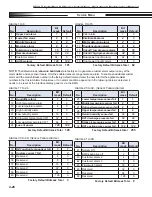
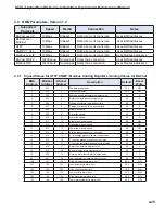
Corresponding Controller to Terminal pLAN Addresses
Controller (I/O board)
1
2
3
4
5
6
7
8
Display Terminal
32
31
30
29
28
27
26
25
You must assign the terminal and controller I/O board addresses for each controller to be grouped. Review Sections
4.6.2.1 to 4.6.2.3 fi rst, before turning power on and the assigning addresses.
Do not interconnect the controllers
together before assigning their terminal and I/O board pLAN addresses.
The fi rst step is to change the terminal address of each controller to 0 referring to Section 4.6.2.1 below. You must set
the terminal address to 0 before you can assign the controller (I/O board) address.
NOTE
: If the terminal remains inactive (no key is pressed) for more than 30 seconds, the group set up procedure is
exited automatically, without saving any changes.
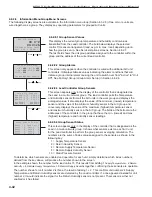
4.6.2.1 Confi gure the Terminal Address
The address of the terminal (display) can only be confi gured if it’s telephone jack is connected to the I/O control
module in the electric box and power is turned on. The factory default value for the display terminal address is 32. To
reassign the terminal address, press and hold the Up ( ), Down
( ) and Enter (
) keys simultaneously for
5
seconds
until the Address Confi guration screen shown below appears with the fl ashing cursor in the top left corner:
1. To change the address of the terminal (Display address set-
ting), press the Enter (
) key once. The cursor will move to
the address fi eld (nn).
2. Use the Up ( ), Down
( ) keys to select the desired value (0),
and confi rm by pressing Enter (
) again.
Display address
setting..........:
nn
I/O Board address:
xx
Address Confi guration
4-32
Summary of Contents for CyberRow DX CRS-042-G
Page 94: ......


