


STULZ CyberRow DX Series Installation, Operation & Maintenance Manual
4-13
The control output signal is matched to the valve. If the
valve typically opens at 2.5 VDC, the control I/O module
will generate the appropriate voltage for opening the
valve starting at the minimum voltage of 2.5 VDC. From
there the signal increases as needed until the valve
position reaches 100% open.
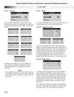
4.4.3.3 Dehumidifying
When dehumidifi cation is called for the blower speed
automatically changes to the dehumidifi cation fan speed
setting. The controller will operate the system in the
cooling mode at full output to strip moisture from the
air. The system will remain in the cooling mode until the
actual relative humidity (or dewpoint) reaches the control
setpoint plus the dehumidifi cation cut-out offset. If the
control temperature drops below the low temperature cut-
out setpoint for the dehumidifi cation mode (temperature
setpoint minus 4°F default), cooling operations will be
stopped.
4.4.4 Air Flow/Fan Speed Control
The
E²
controller treats each EC fan as a variable speed
fan. The controller manages the speed of each fan from
a factory-set minimum up to a factory-set maximum
speed. The minimum fan speed is used whenever
the A/C unit has no cooling operations running. The
maximum fan speed setting is used during times when
the A/C unit is cooling. A dehumidifi cation fan speed
setting is used when the system is in the dehumidifi cation
mode. The speed settings are adjustable in the
Service>Blower>Blower Set Up menu loop (see Section
4.5.5.4.2).
EC fan speed is automatically varied based on
temperature. There are mechanisms to trade-off the
control valve opening versus fan speed. When the
system enters the dehumidifi cation mode, the fan speed
automatically changes to the dehumidifi cation speed
setting.
The
E²
controller's software is equipped with an
operational fail-safe mode. Upon sensing a temperature
sensor failure, the controller signals an alarm. It continues
to develop the fan control outputs by calculating the
averaged value of the remaining sensors to replace the
input value of the failed sensor. If all the temperature
sensors fail, the controller develops the control outputs
based on the entered temperature setpoint value minus a
3°F temperature offset. This allows the CyberRow system
to continue operating while the cause of the problem is
corrected.
The controller continually monitors fan operation.
CyberRow CRS-042 and CRS-084 units are equipped with
a pneumatic air proving system connected to a fl ow switch
that detects the loss of airfl ow when a fan fails to operate.
If one of the fans fails to operate, the controller alerts
the operator with an alarm message and increases the
speed of the remaining two fans to 99.9% to compensate
for the loss of air fl ow. If the fault does not clear, the
fans shut down for 5 seconds and then restart. If the
fault continues, the fans reset a second time. If the fault
does not clear after the second reset the fan(s) which
generated the fault are shut down and the remaining fans
continue operation at 99.9% speed.
In the event of a BMS monitoring/control signal failure, the
E
² controller will default to local operation at the current
setpoints for the fans. The local sensors have priority over
the BMS system.
4.4.4.1 Independent Fan Speed Control
The system controller may be confi gured for
independent, variable fan speed control for managing
upper, middle and lower zone cooling. The controller
continually monitors the actual cold aisle supply air
conditions for each fan zone (upper, middle and lower)
as determined by temperature sensors mounted
locally to each zone inside the CyberRow cabinet and
it adjusts the speed of each fan to meet the supply air
temperature setpoint for that zone. The operator may
select from three independent fan speed temperature
control methods in the Control> Set>Fan Control menu
loop (Section 4.5.4.1). Minimum and maximum fan
speed settings for each fan are user adjustable in the
Service>Blower>Temp Zone Set Up menu loop (see
Section 4.5.5.4.1). The fans will not run at speeds outside
of the envelope established in that menu loop.
4.4.4.1.1 Variance From Average Fan Speed Control
When confi gured for variance from average fan speed
control each fan operates independently. The controller
manages the speed of each fan by comparing the
variance of the fans' local zone temperature sensor to the
overall average temperature measured by the sensors for
all three fan zones. The controller adjusts the speed of
each fan as necessary to meet the supply air temperature
setpoint for that zone.
4.4.4.1.2 Temperature Proportionate Speed Control
The controller adjusts the speed of each fan
proportionally for that zone to meet the supply air
temperature
setpoint. The controller compares the
variance of each temperature zone to the temperature
setpoint and develops a proportional control output to
modulate the speed of each fan to meet the supply air
temperature setpoint for that zone.
4.4.4.1.3 Manual Speed Control
The controller continually controls the speed of each
fan to values manually entered in the system controller
Control>Set>Fan Control menu loop (Section 4.5.4.1)
without regard to the temperature setpoint.
Summary of Contents for CyberRow DX CRS-042-G
Page 94: ......


