33
CCU 90 CW
CCD 90 CW
© STULZ GmbH – all rights reserved EN/06.2021/G23
minispace cw original instructions
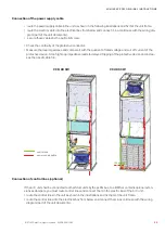
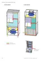
Connection of the power supply cable
control line
power supply cable
• route the power supply cable in the unit as shown in the following illustrations and fix it at the unit frame.
• route the electric cable into the electrical box from below and connect it, in accordance with the wiring dia-
gram (part of the unit documents).
• secure these cables by the pull relief screw.
Connection of control lines (optional)
If the A/C unit shall be connected to other Stulz units by the pLAN bus, to a BMS or contains opional exten-
sions as dampers, you must route control lines and connect them in the electric box of the A/C unit.
• route the control lines in the unit as shown in the illustrations and fix them at the unit frame.
• route the control lines into the electrical box from below and connect them in accordance with the wiring
diagram (part of the unit documents).
• Check the continuity of the protective conductor.
• Measure the loop impedance and compare it with the quotient of rated voltage and cut-off current of the
protective device. A too high loop impedance leads to delayed tripping of the protective device and increa
-
ses the risk of cable fire.


