Z001019/0_6_July 2008
Page FUEL SYSTEM - 25
SERVICE MANUAL MARINE ENGINES
03 FUEL SYSTEM
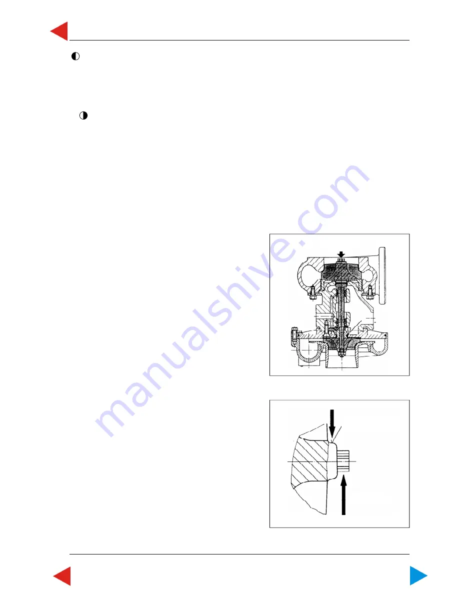
05.02 ill.1
05.02 ill.2
03.05.02
Check bearing clearance
Measure end clearance:
1
Put test prod of dial gauge onto face of turbine wheel
hub.
2
Push cursor downwards and set dial gauge to "0".
3
Push cursor against dial gauge and note deflection of
pointer.
permissible end clearance: max. 0.16 mm +/-0,01
Measure radial clearance:
NOTE:
Determination of radial clearance is
only required turbine-sided.
1
Put test prod of dial gauge onto center of retainer
cone of turbine wheel.
2
Pull turbine wheel hub upwards by means of spring
balance.
Measuring strength 50 N.
3
Note deflection of pointer.
4
Repeat measurement, by turning cursor by 90°.
Permissible radial clearance: max. 0.42 mm +/-0,04
measuring point
measuring
strength
location point
of dial gauge
prod
For 4 cyl. engines only (item 1-2)
1
Tighten 4 hexagon nuts of turbocharger flange with a torque of
25 Nm +/-2
.
2
Tighten 2 screws for fixing the flange of oil return pipe with a torque of
10 Nm +/-1
.
Tighten hollow screw with
25 Nm +/-3
.
For 6 cyl. engines only (item 3-6)
3
Tighten 4 hexagon nuts of turbocharger flange by means of torque wrench No. 2300743/0 and tree-
handled socket wrench No. 2300744/0 with a torque of
40 Nm +/-4
.
4
Tighten 2 screws for fixing the oil return pipe flange with a torque of
23 Nm +/-2
.
Tighten hollow screw with
40 Nm +/-4
.
5
Tighten hollow screw of vent pipe (cooling circuit) with a torque of
20 Nm +/-2
. Maintain horizontal
position of banjo fitting while tightning hollow screw.
6
Fill closed cooling circuit, refer to 05.00.08
ToC


