© 2008 Stevens AeroModel.
Page 27 of 52
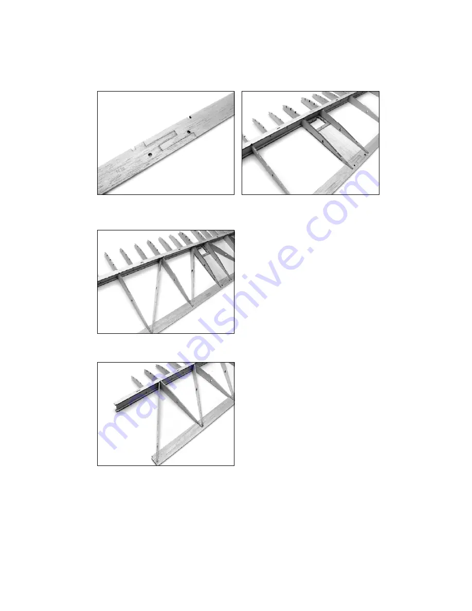
12. Join the 1/8 in. trailing edge (previously assembled in step 1) to the wing assembly as illustrated below. The
finger joint of TE1 should center between right and left ribs R1. Verify that each rib is fully seated within the
corresponding notch at trailing edge and retain trailing edge by tack gluing at tab and notch locations.
13. Locate the 3/32 in. balsa W2 wing trussed sub ribs (sheet 07/21) and install to assembly between the right and
left rib bays formed by R1/R2 and R2/R3 as illustrated below.
Next locate the 3/32 in. balsa W3 wing trussed sub ribs (sheet 07/21) and install to assembly between the right
and left rib bays formed by R3/R4 and R4 and end of wing as illustrated below.
With the trussed sub ribs installed to both right and left sides of the wing assembly, square wing to flat work
surface and tack glue at tab and notch locations and the interface of trussed sub ribs to the back side of the
wing spar.


