© 2008 Stevens AeroModel.
Page 38 of 52
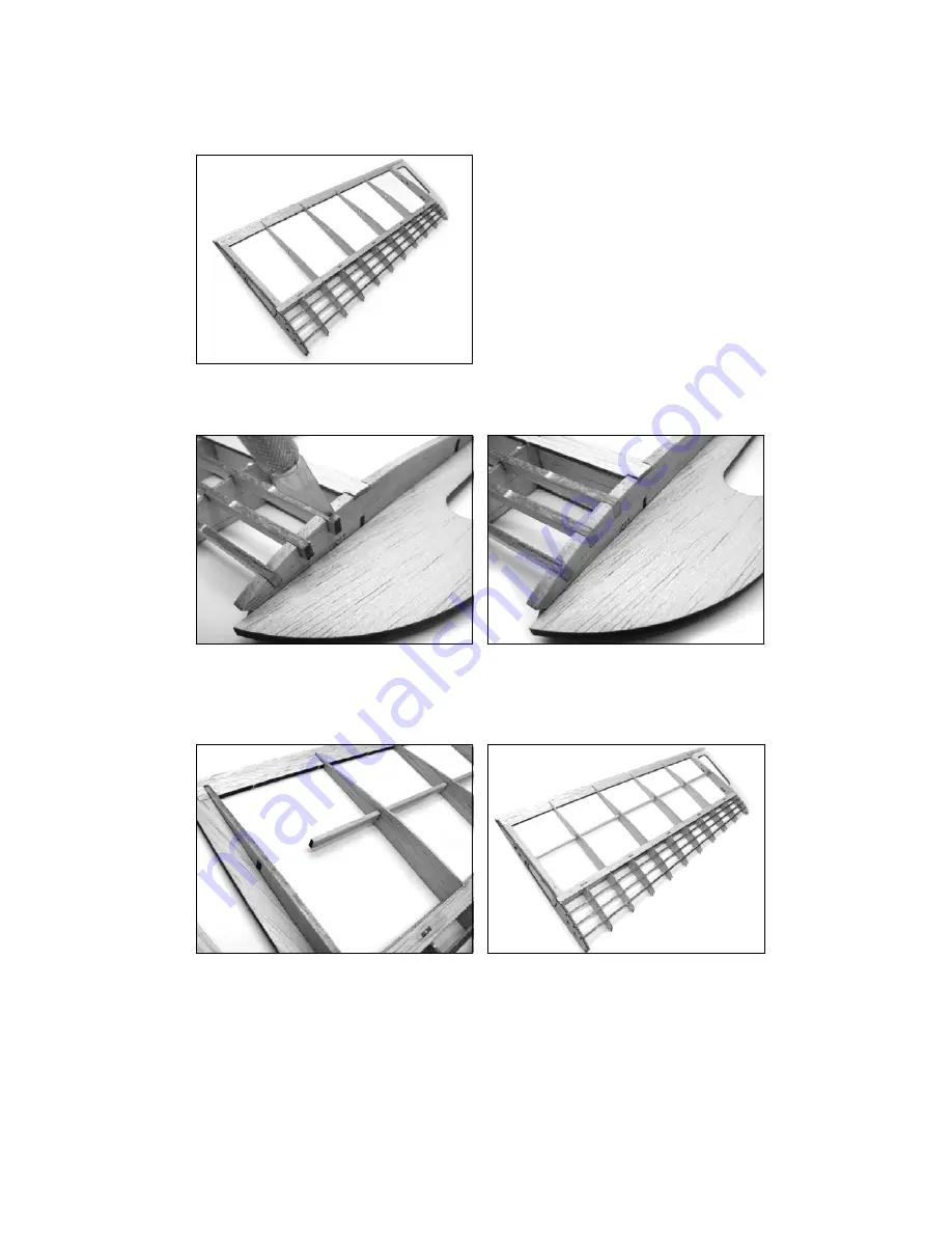
14. Install the remaining 3/32 in. balsa turbulators T5 and T6 (sheet 05/21) and fit / tack glue to the wing tip
assembly in their respective positions.
15. The turbulators have been slightly oversized to allow for variance in wing assembly. Trim excess turbulator
stock as it extends beyond ribs R6 and R11, then sand flush with outside surface of rib.
16. Locate and fit/sand 1/8 in. balsa sub spar W5 (sheet 09/21) to fit notches within ribs of wing tip assembly and
install to wing tip spanning ribs R6 through R11 as illustrated below. Note: as with the turbulator stock in
previous steps W5 features an “<-“ to designate which end has been cut to match the angle of the dihedral
break rib R6.


