42
EN
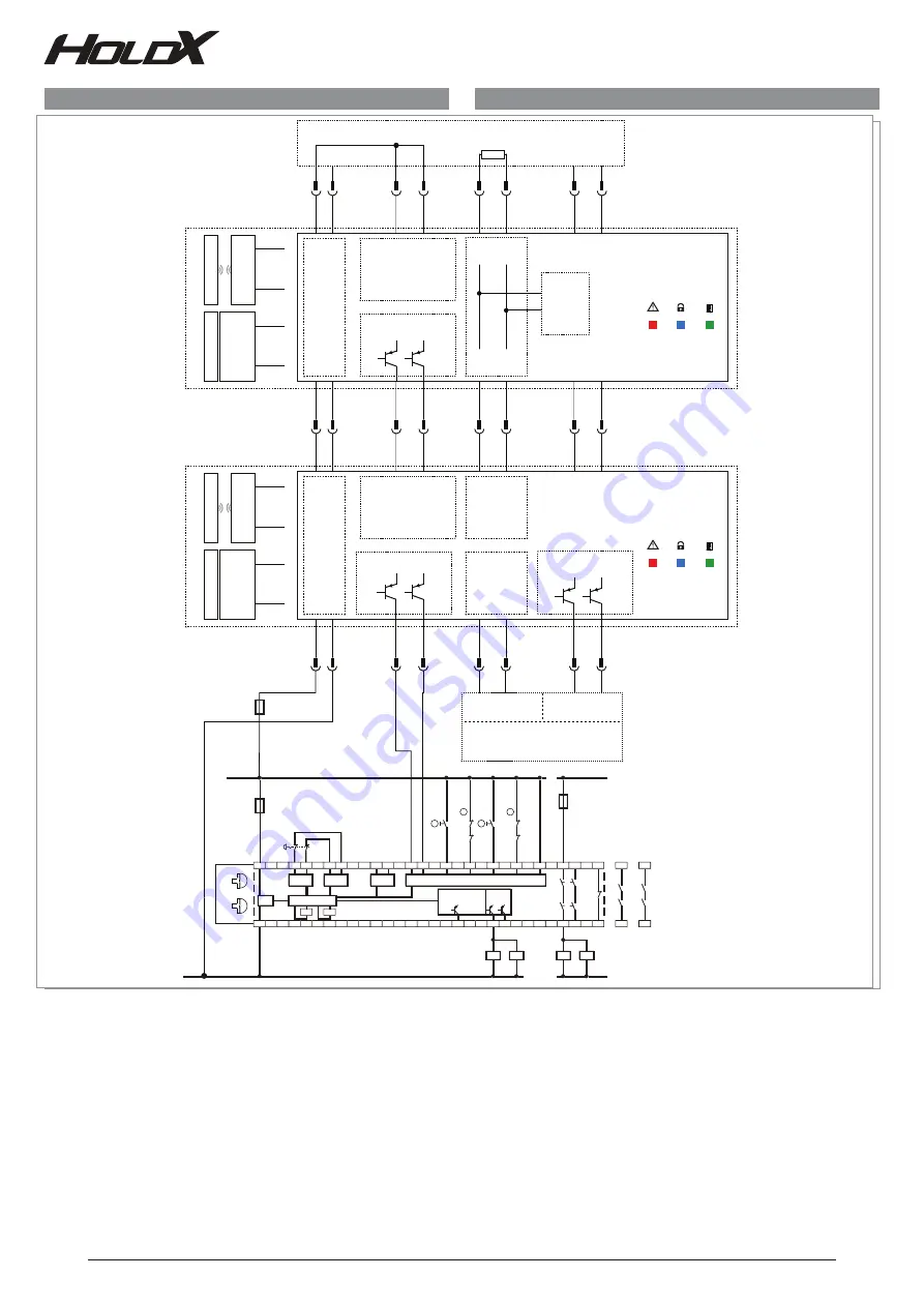
Fig. 21: Connection example 2
The safety relay series X2 monitors 2 safety functions.
Safety function 1: Emergency stop circuit with manual reset button
Safety function 2: Series connection of one HOLDX master and one HOLDX slave with manual reset button.
The Termination Plug R120 is connected to the slave's X2 connection. The safety outputs Pin 2 (X1) and Pin 4 (X1) of the HOLDX master are connected to the safety relay X2 series, con-
nection S42 and S32. The safety relay was set to setting 1 for safety function 1 and setting 3 for safety function 3. The connector Serial OUT of the HOLDX master Pin 7 (X1) and Pin 8 (X1)
and Serial IN Pin 5 (X1) and Pin 6 (X1) are connected to a PLC.
Safety inputs
HOLDX R Termination Plug
Safety outputs
OSSD2 IN
OSSD1 IN
+24
V DC
+24
V DC
sa
fe
ty sensor
coded
M
ag
net
A
nchor pl
ate
A
ctu
ator
OSSD1 OUT
OSSD2 OUT
1
3
2
4
7
8
5
6
120 R
1
X2
X1
3
2
4
7
8
5
6
Safety inputs
CAN
CAN H
CAN L
OSSD2 IN
OSSD1 IN
+24
V DC
+24
V DC
M
ag
net
1
0
V
3
2
4
7
8
5
6
1
X2
X1
0
V
3
5
6
Standard-PLC
Input
Output
1
3
2
4
2
4
7
8
7
8
5
6
0 V
HOLDX RL2-CC-S
Slave
HOLDX RL2-CS-P8-...-B
Master
CAN H
CAN L
CAN H
CAN L
CAN
0
V
0
V
Sa
fe
ty sensor
coded
A
nchor pl
ate
Ac
tu
ator
Error
Gate
Lock
Error
Gate
Lock
D
ata
Clock
Serial OUT
D
ata
Clock
Safety outputs
OSSD 1
OSSD 2
Serial IN
R
H2
X7
X3
A1
S22
S11
A2
S21
X2
Q1 Q2
Y1
S12
KC
KD
+24VDC
safety
function 1
safety
function 2
KA
KB
KA
KB
F2
F1
S42
S31 S41
S32
K1
K2
KC
KD
X5
X4
K2
K1
KC
KD
23
13
41
24
14
42
KA
KB
N
L1
R
H2
a)
b)
c)
d)
e)
f)
d)
a)
g)
mode 1
mode 2
1
h)
4
h)
Safety relay series X2
a) safety inputs
b) safety outputs, safety function 2
c) signal output
d) clock output
e) CPU
f) power supply
g) safety output, safety function1
h) rotary knob for programming
SP-X-71-002-06
+ 24
VDC
0
V


