SplashMe Automation Controller 1.0 | Installation and Operating Instructions
© Nymet Innovations Pty Ltd 2019 | Revised November 2019
12
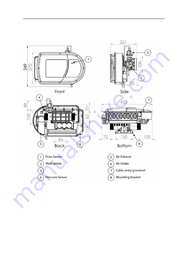
2.3 – Technical specifications
Multi-Function Button
Page 1: ...OPERATING INSTRUCTIONS SPLASHME AUTOMATION CONTROLLER 1 0 SM AC 1 0 Designed and manufactured in Australia splashmepool com au Nymet Innovations Pty Ltd 2019 Patent Pending PCXT AU2018 050995 Approva...
Page 2: ...ce is not mounted near pool chemicals as fumes may damage or corrode some components Always store chemicals in a cool dry and well ventilated space always from other hazardous chemicals in accordance...
Page 3: ...t is believed to be accurate and reliable as at date of printing However Nymet Innovations assumes no responsibility for the use of this material Nymet Innovations Pty Ltd reserves the right to make c...
Page 4: ...should be a person with sufficient experience in pool equipment installation and be approved to install the SplashMe Automation Controller so that all the instructions in this manual can be followed e...
Page 5: ...er and flow System pressure Solar and water temperature Water quality and chemistry pH ORP Using the SplashMe App users have complete control to set automatic schedules or operate manually A single sp...
Page 6: ...SplashMe Automation Controller Warning WARNING indicates a hazard which if not avoided could result in damage to the SplashMe Automation Controller it not functioning properly and or physical human No...
Page 7: ...cess mode is when the SplashMe Automation Controller connects directly with the user App without the use of a gateway router Blue solid light Device has established an internet connection and is commu...
Page 8: ...0 Installation and Operating Instructions Nymet Innovations Pty Ltd 2019 Revised November 2019 7 1 5 List of connected equipment Outlet ID Connected Appliance Filter Pump AUX 1 AUX 2 AUX 3 AUX 4 AUX 5...
Page 9: ...Section 3 Installation 18 3 1 Selecting suitable mounting location 18 3 2 Installing the multi probe 19 3 3 Mounting to wall 20 3 4 Fixing the SplashMe Automation Controller to the wall bracket 22 3...
Page 10: ...5 2 4 Auxiliary connections actuator valves equipment 15A 3phase 44 5 2 5 12VDC peristaltic pump for acid dosing 48 5 2 6 Gas heater or electric heat pump 49 5 3 Powering up 50 Section 6 Local control...
Page 11: ...robe the SplashMe Automation Controller can operate connected dosing equipment to automatically dose water with both acid via a standard peristaltic pump and chlorine via a saltwater chlorinator or pe...
Page 12: ...Controller and void warranty Number Description QTY 1 SplashMe Automation Controller 1 2 SplashMe Multiprobe with storage cap and storage solution 1 3 Wall bracket 1 4 Mounting screws 4 5 Locking scre...
Page 13: ...SplashMe Automation Controller 1 0 Installation and Operating Instructions Nymet Innovations Pty Ltd 2019 Revised November 2019 12 2 3 Technical specifications Multi Function Button...
Page 14: ...d SELV supply loads only 12VDC acid dosing output WARNING All output cables and sockets must be disconnected when not in use SENSORS pH sensor ORP sensor Water temperature sensor Ambient temperature s...
Page 15: ...rating Temperature 0 60degC ORP Range 2000mV ORP Sensor 99 9 Pure Gold 4mm x1mm Pin Accuracy 50mV Temperature sensor Operating Temperature 20 80degC Temp Sensor 316 Marine grade stainless steel Accura...
Page 16: ...A Max Outputs VSD 240V 9 0A Max AUX 1 3 240V 50Hz 10A Max AUX 4 240V 50Hz 10A Max AUX 5 8 24V 5A Each Doser 12VDC 2A Switched Peristaltic Pump Output Warning Auxiliary inputs Auxiliary inputs to be co...
Page 17: ...lashMe Automation Controller has an inbuilt ORP sensor It works by measuring the dissolved oxygen in the water More contaminants in the water result in less dissolved oxygen because the organics are c...
Page 18: ...p to filter pool water Hand Saw Hand saw suitable for cutting PVC pipe PVC Priming fluid Used to clean and prepare pipe ready for gluing PVC Glue Type P Ensure PVC glue is Type P which is suitable for...
Page 19: ...greater service life Choose a location that best allows for the next three requirements Plumbing requirements The SplashMe Automation Controller must be plumbed inline directly after the sand filter...
Page 20: ...soon as it is installed Instructions 1 Unscrew the black locking nut anti clockwise to remove the protective cap 2 Discard the storage solution rinse the cap in water and then dry the cap with a soft...
Page 21: ...Ensure the bracket is level and then secure to the wall using the 4 x 50mm 316 stainless steel countersunk screws provided See Fig 3 Note When securing to a hollow wall it is recommended timber studs...
Page 22: ...n the wall with the hanging hooks pointing up 2 Ensure wall bracket is level and mark the 4 outer holes with a pencil See Fig 2 3 Using an 8mm masonry drill bit drill the marked holes to the depth of...
Page 23: ...Automation Controller from the box and line up the 3 slots in the rear bracket with the 3 hooks on the wall bracket 2 Allow the SplashMe Automation Controller to hang on the 3 hooks so the bottom two...
Page 24: ...essential that the SplashMe Automation Controller be plumbed in line with the pool filtration equipment Instructions 1 Install the 2 supplied RED Viton O rings to the inside of the female end of the...
Page 25: ...the required pressure pipe to create a connection path from the filter Return outlet and the SplashMe Automation Controller inlet right side Pressure pipe and 90degree bends will be needed to make th...
Page 26: ...SplashMe Automation Controller 1 0 Installation and Operating Instructions Nymet Innovations Pty Ltd 2019 Revised November 2019 25...
Page 27: ...connected the SplashMe App will alert users when the filter needs to be cleaned or a backwash needs to be performed 1 Locate the existing pressure gauge on the sand filter cartridge filter body and r...
Page 28: ...pump Before connecting the pump to the SplashMe Automation Controller the pump will need to be installed as per below instructions Mounting the device Instructions 1 Choose a location where the dose p...
Page 29: ...booster pumps Instructions 1 Drill a 12mm hole into the 40mm or 50mm pipe 2 Insert the supplied rubber grommet so the contour follows the pipe curve 3 Push in the supplied nipple into the grommet unti...
Page 30: ...the tapered nipple 6 Align the two locking tabs on the filter basket with the slots in the clamp and then press the two together until the locking tabs engage 7 Feed the filter basket into the acid c...
Page 31: ...SplashMe Automation Controller 1 0 Installation and Operating Instructions Nymet Innovations Pty Ltd 2019 Revised November 2019 30...
Page 32: ...r requires a total of 3 x 10A RCD protected socket outlets each connected to a separate 16A circuit and circuit breaker The socket outlets need to be mounted within 1 5 m of the SplashMe Automation Co...
Page 33: ...Check local codes NEC and or local installation codes for installation requirements 1 A 6mm bonding terminal is provided on the back of the SplashMe Automation Controller This terminal is connected to...
Page 34: ...AUX 1 3 This input is required to be connected to an RCD protected socket outlet that is on a dedicated 16A circuit and circuit breaker Use this plug if equipment will be connected to AUX 1 AUX 2 or A...
Page 35: ...eed filter pump into the filter pump VSD outlet the SplashMe Automation Controller will power the pump and automatically vary the speed of the filter pump to optimise energy consumption and pool sanit...
Page 36: ...chlorinator to achieve the set levels Most saltwater chlorinators are equipped with a time clock Any Chlorinator timeclocks will need to be disable prior to connecting to the SplashMe Automation Contr...
Page 37: ...ll doses as required Instructions 1 Select any of the auxiliary outputs AUX 1 2 3 and 4 to control the peristaltic dosing pump Alternatively if required a low voltage auxiliary contact AUX 5 6 7 or 8...
Page 38: ...plashMe Automation Controller will then control the solar heating to achieve and maintain the pre set level If no filter pump schedule is running the SplashMe Automation Controller will periodically m...
Page 39: ...1 0 Installation and Operating Instructions Nymet Innovations Pty Ltd 2019 Revised November 2019 38 Instructions 1 Check the power requirements of the solar pump and connect to the most suitable outp...
Page 40: ...booster pump is used to pull water from the filter pump suction line and divert it to the roof The filter pump will always need to operate in conjunction with the Solar booster pump to operate the so...
Page 41: ...requirements and connect to the most suitable output using the supplied adaptor Note For installation instructions on connecting the roof temperature sensor see section 5 2 3 Existing solar temperatu...
Page 42: ...liary outlets AUX 1 2 3 or 4 can be used to control equipment additional to those mentioned above Examples of additional 240v auxiliary equipment includes but is not limited to water features spa blow...
Page 43: ...fitting 1 Ensure that the O Ring is in position and clear of any debris 2 Place the front cover in position and ensure the Multi Function button has come through the cover and can be pressed See diagr...
Page 44: ...ioned above Examples of additional auxiliary equipment includes but is not limited to actuator valves relays heater controls dosing pumps Auxiliaries 5 6 7 8 are voltage free relays They are generally...
Page 45: ...provide the most accurate temperature conditions of the solar system Installing and connecting the sensor Instructions 1 Attach the stainless steel temperature sensor to a piece of rubber silicone or...
Page 46: ...per manufactures specification 2 Remove the front cover of the SplashMe Automation Controller section 5 2 2 3 Run the actuator and power supply wires through the bottom cable grommet 4 Group the negat...
Page 47: ...n and Operating Instructions Nymet Innovations Pty Ltd 2019 Revised November 2019 46 Warning All electrical connections and installations to be done by a licenced electrician AUX 5 8 is for the connec...
Page 48: ...upply Loads only When using the SplashMe Automation Controller to control larger equipment such as 15A pumps or 3 phase equipment a licenced electrician will be required to configure a relay contactor...
Page 49: ...mation Controller will automatically maintain a pre set pH level entered in the App settings Whenever the filter pump is functioning the SplashMe Automation Controller measures the pH of the water usi...
Page 50: ...perature on the heater to maximum as the in built thermostat will replace the heater thermostat The SplashMe Automation Controller will automatically maintain a pre set temperature entered in the App...
Page 51: ...s Main supply Instructions 1 Plug in and switch on the Primary Input lead The SplashMe Automation Controller will go through a pre configuration power up routine The 3 indicator lights will initially...
Page 52: ...ecessary to toggle the device between connection modes To switch modes Press and hold the multi function button until 2 quick beeps sound This will toggle the SplashMe Automation Controller between th...
Page 53: ...lashMe Automation Controller will have the RED light illuminated Refer to the app for info on the error If the error is related to the main filter pump it cannot be cleared remotely Clearing motor rel...
Page 54: ...he installer will need to download the SplashMe App from either Apple App or Google Play stores Google Play Store https play google com store apps details id au com nymet splashme Apple App Store http...
Page 55: ...er basket and clean if required Remove any floating or settled debris Check water level is in the middle of the skimmer mouth opening for correct pump operation Weekly twice weekly for high use period...
Page 56: ...Controller 2 Close valves if your probe is below water level 3 Unscrew the black locking nut and remove the multiprobe from the port at the back of the device 4 Holding the probe by the cable gently s...
Page 57: ...ng every 12 months Instructions Ensure system is off and close check valves if system is positioned below water level Disconnect feed tubing from input and output of dosing pump Be aware of chemicals...
Page 58: ...t barbed nipple and align round edge of barbed nipple with locator guides and gently pushing tube past each roller cam one at a time Warning Be aware of chlorine and acid residue in both squeeze tubes...
Page 59: ...omation Controller 1 0 Installation and Operating Instructions Nymet Innovations Pty Ltd 2019 Revised November 2019 58 Insert the output barbed nipple into the locator round edge first Replace cover a...
Page 60: ...on Controller 1 0 Installation and Operating Instructions Nymet Innovations Pty Ltd 2019 Revised November 2019 59 Section 9 Troubleshooting See SplashMe website www splashmepool com au support for fur...
Page 61: ...omation Controller 1 0 Installation and Operating Instructions Nymet Innovations Pty Ltd 2019 Revised November 2019 60 Section 10 Warranty Refer to Warranty Policy on the SplashMe website www splashme...
Page 62: ...or email info splashmepool com au The contents of this manual will be periodically updated or revised due to product updates The latest version of the SplashMe Installation User Guide will be availabl...
Page 63: ...SplashMe Automation Controller 1 0 Installation and Operating Instructions Nymet Innovations Pty Ltd 2019 Revised November 2019 62 NOTES...
Page 64: ...SplashMe Automation Controller 1 0 Installation and Operating Instructions Nymet Innovations Pty Ltd 2019 Revised November 2019 63...