background image


Technical data 


— 16 

SPECTRO GENESIS FES 27 — 17.07.2019 
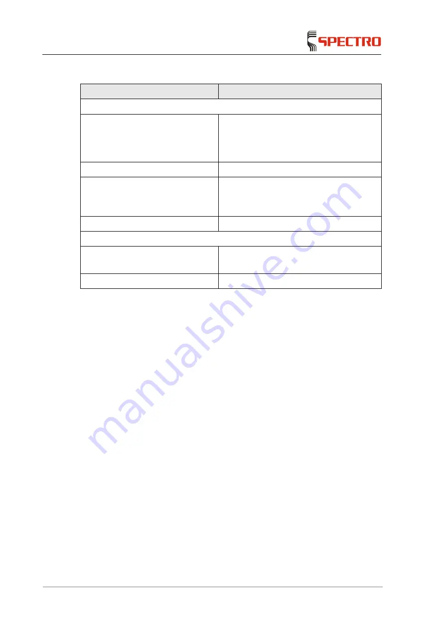


Description 

Value 

Argon gas connection 

Inlet pressure during operation 

6–8 bar (87–116 psi)  

7 bar (101 psi) recommended 

A maximum Ar inlet pressure of 8 bar (116 psi) 
must not be exceeded. 

Quality 

≥ 4.6 (99.996 %) 

Optical system gas flushing rate 

0 L/min (off) 

0.5 L/min (low) 

1 L/min (high) 

Plasma gas consumption 

≤ 25 L/min  

Extraction (continuous) 

Plasma torch box 

Depending on the ambient temperature 

100 – 140 m³/h; 59 – 82 ft³/min 

Generator 

250—300 m³/h; 150–177 CFM 


Summary of Contents for FES 27

Page 1: ...Möglicherweise wurde die Datei verschoben umbenannt oder gelöscht Stellen Sie sicher dass die Verknüpfung auf die korrekt SPECTRO GENESIS FES 27 Optical emission spectrometer with inductively coupled plasma excitation Original operating instructions ...

Page 2: ......

Page 3: ...ortation Setting up 17 4 1 Space requirements 17 4 2 Set up 18 4 3 Ambient temperature 18 4 4 Dust load 19 4 5 Transport 19 4 6 Storage 20 4 7 Gas supply 21 4 8 Exhaust air to the outside 22 5 Operation 23 5 1 Overview of controls 23 5 2 Preparing the instrument for use 23 5 3 Switch on the instrument ready for operation plasma start 24 5 4 Switch off the instrument plasma 25 5 5 Carrying out the ...

Page 4: ...he load coil 39 6 7 Cleaning the plasma control fiber optics 40 6 8 Optimizing the nebulizer gas flow 41 6 9 Cleaning the Side On Plasma Interface SPI 42 6 9 1 Removing the SPI 42 6 9 2 Clean the lens and the SPI 43 6 9 3 Install the lens and the SPI 44 6 10 Pump tubing maintenance 45 7 Troubleshooting 46 8 Spare parts and consumables 50 9 De commissioning 50 10 Manufacturer address 50 11 EC Decla...

Page 5: ...mple dissociate into atoms The atoms are excited and partly ionized The excited atoms and ions emit an element specific radiation A transfer optics feeds this radiation into the optical system The emitted radiation is diffracted into its spectral components in the optical system The intensity is measured using semiconductor detectors CCD After processing the measuring signals in the instrument the...

Page 6: ...019 1 3 Overview 1 3 1 Instrument Fig 1 Nr Component Nr Component 1 Air filter 7 Peristaltic pump sample transport 2 Torch box 8 Connections 3 Window to observe plasma 9 Plasma off 4 Analysis chamber 10 Main switch 5 Torch box exhaust 11 PC 6 Generator exhaust ...

Page 7: ...Connections right hand side Fig 2 No Component No Component 1 PC connection TCP IP 4 Power cable 2 Argon connection 5 Support rod bracket 3 Oxygen connection option 1 3 3 Peristaltic pump Fig 3 No Component 1 Leadthrough to sample introduction chamber 2 Peristaltic pump ...

Page 8: ...ESIS FES 27 17 07 2019 1 3 4 Sample introduction system Fig 4 No Component No Component 1 Clamp 5 Nebulizer 2 Spray chamber 6 Argon connection 3 Spray chamber mounting 7 Sample introduction connection from peristaltic pump 4 Drain connection ...

Page 9: ...s installed vertically with radial plasma viewing SOP Fig 5 No Component No Component 1 Extraction box housing and torch 7 Plasma control fiber optics 2 Plasma interface 8 Plasma auxiliary gas connection 3 Load coil 9 Contact pin 4 Plasma torch 10 Connection to sample introduction system 5 Plasma torch bracket 11 Clamp 6 Bracket ...

Page 10: ...ols used The following symbols are used in these abbreviated operating instructions and or on the instrument If required additional important information is available in connection with these symbols General warning sign Warning of hazardous voltage Warning Hot surface Warning of toxic substances Warning Sharp edges Warning Optical radiation Warning Risk of suffocation Warning of hand injury ...

Page 11: ...cturer During the operation and while performing maintenance tasks compliance with safety instructions and accident prevention regulations is mandatory This is specified in DIN EN 61010 or a comparable national standard The safety measures must be checked following every technical maintenance or repair activity This check is to be performed in accordance with VBG4 DIN EN 61010 or a comparable nati...

Page 12: ...ted on networks with PE protective conductor PE The instrument may be operated only in a dry environment protection class IP 22 DIN 40050 If an instrument is positioned on a sloped surface and equipped with wheels it may roll away during the operation Secure the instrument while in operation This applies also when the instrument is being transported Compliance with the relevant safety regulations ...

Page 13: ...njury and health hazard Hazardous sample residues may be present in the sample introduction system and waste containers Take suitable safety precautions before working on it Observe the safety data sheets as well as the H and P phrases that apply to the sample material and or the solvent used Warning of toxic substances Vapors may be generated from the sample material These may be toxic and or cor...

Page 14: ...ary install oxygen sensors Warning Optical radiation The plasma emits UV radiation A protective pane is used to shield from the radiation Operate the instrument only with the protective pane in place and the door closed Information A high frequency emitter is used to operate the ICP dependent on the type of model The electromagnetic emission is below the legally specified limit values Please point...

Page 15: ...nt power consumption 3 5 kVA Instrument required line protection 30 32 A inertial Sound pressure level 58 dBA Stability according to DIN EN 61010 1 compliant if change of position 10 Storage conditions 2 40 C 36 104 F Operating range permissible ambient temperature 5 35 C 41 95 F Recommended temperature range for reaching the specified performance 18 25 C 64 77 F maximum temperature gradient T 3 C...

Page 16: ...ar 101 psi recommended A maximum Ar inlet pressure of 8 bar 116 psi must not be exceeded Quality 4 6 99 996 Optical system gas flushing rate 0 L min off 0 5 L min low 1 L min high Plasma gas consumption 25 L min Extraction continuous Plasma torch box Depending on the ambient temperature 100 140 m h 59 82 ft min Generator 250 300 m h 150 177 CFM ...

Page 17: ...ansport the instrument If possible other lifting and transport equipment shall be used The instrument shall not be tilted more than 10 degrees from its vertical position Unpacking installation setup and connection of the instrument may only be performed by service personnel that is authorized by the manufacturer Notice Damage to instrument If the instrument is to be moved to another place of insta...

Page 18: ...sponding dimensions and load carrying capacity is required see page 15 In addition to the space required by the SPECTRO GENESIS FES 27 some space is needed for the gas supply unless fixed gas connections are available The SPECTRO GENESIS FES 27 is operated exclusively from the front and from the right hand side of the housing Sufficient space should be provided for the computer workstation keyboar...

Page 19: ...ust also be set up in an environment which is free from corrosive vapors 4 5 Transport Notice Damage to instrument If the instrument is to be moved to another place of installation after set up there is a risk of damaging the instrument Contact the SPECTRO Service Department in this matter The instrument must be raised prior to transport by forklift A special transport device has been provided for...

Page 20: ...de Fig 8 Warning Risk of injury due to falling or tipping loads The instrument weighs approx 115 kg and the weight is not evenly distributed Falling or tipping the instrument can result in serious injuries Always use a hoist to lift the instrument The instrument can be raised 4 6 Storage Storage conditions Unit must be stored in a dry place Room temperature 2 C 40 C 35 6 F 104 F Avoid storing the ...

Page 21: ...pressure of 8 bar 116 psi must not be exceeded The tubing for the Argon supply is included in SPECTRO s scope of supply 5 m long OD ID 8 6 mm This tubing is screwed to the connection on the right hand side of the instrument The connection to the instrument is included in the scope of supply The connector on site is customer specific and therefore not part of the delivery The following flow quantit...

Page 22: ...free exhaust chimneys must be connected with the laboratory exhaust system using a non flammable flexible and corrosion resistant hose ID 100 mm The fan must be resistant to chemicals and designed to operate at temperatures up to 80 C 176 F The exact position of the exhaust nozzles is shown in the figure below All installation must be performed in a professional manner and in accordance with appli...

Page 23: ...roceed as follows 1 Instructions on how to install the Plasma torch and the sample introduction system see page 33 2 Open the Argon supply valve Set the Argon pressure to 7 0 bar The plasma cannot be started at a pressure of 6 0 bar A corresponding error message will be displayed 3 Ensure that the extraction system is activated and that the specified exhaust capacity is reached 4 Ensure that all f...

Page 24: ... the stabilization period see no 7 To switch on the instrument proceed as follows 1 Turn the main switch to On 2 Switch on the computer The operating system is booted 3 Start the instrument s software program ICP ANALYZER PRO after the operating system has been completely booted Allow the instrument to stabilize for at least 3 hours after switching it on optical system Ensure that the operating te...

Page 25: ...ch set to On This ensures good long term stability during the measurement To switch off the instrument proceed as follows 1 Flush the sample introduction system for approx 10 minutes with a suitable blank solution e g distilled water for aqueous applications This avoids crystallization in the sample introduction system 2 Select the Solid State Generator dialog in the instrument control parameter d...

Page 26: ...e elements In addition it reduces the time necessary for stabilization after the start of plasma 6 Loosen the pressure clamps of the peristaltic pump and depressurize the pump tubing by removing it from the retaining clamps 7 Switching the instrument off Turn the main switch to Off see note Switch off the exhaust system The instrument is switched off Information If steps 5 and 7 are omitted the in...

Page 27: ...ing samples Wavelength calibration of the optical system The wavelength calibration of the optics is mandatory after a software message wavelength drift after it has been switched on and after the temperature stabilization before setting up a new method before proceeding with high precision measurements I Aqueous applications The wavelength calibration of aqueous applications requires a solution o...

Page 28: ...cial solutions for the wavelength calibration optimization or equipment check are available from your local SPECTRO organization In order to proceed with the wavelength calibration follow the instructions below 1 Start the plasma 2 Flush the sample introduction system for approx 10 minutes Use distilled water for aqueous applications 3 Select the wavelength calibration symbol in the navigation too...

Page 29: ... the standards with the lowest concentrations and then the ones with higher concentrations 3 Use the peristaltic pump in order to feed the corresponding sample to the sample introduction system 4 Click on the Measurement button Once the measurement has been completed stop the measurement and click the Finish button 5 Activate the next standard in the list 6 Click again on the Measurement button 7 ...

Page 30: ...book and a method must be created first To do this use the online help 2 Feed the sample to be measured to the sample introduction system by means of the peristaltic pump 3 Press the Measure button in order to start the measurement The measurement is carried out automatically When the measurement is complete the results are displayed on the screen Press the Finish button to terminate the measureme...

Page 31: ...he instrument proceed with the following maintenance tasks Start of work Tasks to be performed Check the gas supply The min pressure in the bottle is 40 bar Peristaltic pump tubing and sample introduction system tubing Check for damage and flow Weekly maintenance work Plasma control fiber optics Check for damage and contamination Clean or replace if required see page 40 Nebulizer Check for contami...

Page 32: ...Maintenance 32 SPECTRO GENESIS FES 27 17 07 2019 Further maintenance work Load coil Check for corrosion Clean if required see page 39 Pump tubing Check for damage Replace if required see page 45 ...

Page 33: ...ution or its vapors Clean only the quartz glass of the plasma torch in the cleaning solution To clean the plasma torch proceed as follows 1 Switch off the plasma 2 Release the connections on the torch 3 Loosen and remove the clamp s between the plasma torch and the spray chamber 4 Release the torch holder 5 Remove the plasma torch 6 Clean the torch To do this remove the tubing with the metal fitti...

Page 34: ...Hold the torch 2 so that the gas connections 3 point to the left II Insert the torch into the load coil 1 until the pin 4 is above the bracket 5 III Rotate the gas connections to the right Lower the torch carefully until the pin rests on the bracket IV Close the holder 6 Fig 11 The plasma torch has been cleaned 5 6 3 4 1 2 ...

Page 35: ...es with a suitable blank solution e g distilled water for aqueous applications 2 Switch off the plasma 3 Release the clamp s between the torch and the spray chamber 4 Carefully pull the spray chamber to the bottom SOP in order to separate the spray chamber from the torch 5 Disconnect all other connections from the nebulizer and the spray chamber 6 Release the mounting clip and carefully remove the...

Page 36: ... Cleaning the spray chamber standard Scott Chamber Warning Risk of injury There may be acid residues or other hazardous residues from sample material in the nebulizer and the spray chamber Observe the corresponding information on hazardous materials Warning Sharp edges Glass parts may break when handled incorrectly and cause cutting injuries Proceed with due caution and or take appropriate safety ...

Page 37: ...ean the spray chamber First use a suitable diluted acid solution e g hydrochloric acid or nitric acid 1 10 Hazardous substance Observe the corresponding information on hazardous materials After this use a laboratory cleaning agent for removing traces of fatty substances streaks if required Now flush the spray chamber thoroughly with distilled water 10 Reinstall the components 11 Optimize the nebul...

Page 38: ...p the Solid State Generator menu item via the instrument control parameter dialog 3 Adjust the nebulizer gas flow determined for the nebulizer 4 Using a spray bottle force distilled water through the nebulizer connection for sample introduction The spray coming out must be evenly V shaped If this is not the case the nebulizer may be clogged and must be cleaned see page 35 Fig 12 5 Reinstall the co...

Page 39: ...ncing work on them The load coil may corrode because of the sample vapors In order to clean the coil proceed as follows 1 Switch off the instrument 2 Remove the Plasma torch see page 33 3 Clean the load coil with a small brush e g a toothbrush and a grinding paste e g toothpaste Do not bend the load coil 4 Remove the grinding paste completely from the load coil 5 Reinstall the components The load ...

Page 40: ...ry hot Let the components cool for 10 to 15 minutes before commencing work on them Follow the steps below to clean the fiber optics 1 Loosen the grub screw on the fiber optics holder 2 Pull the fiber optics out of its holder Fig 13 3 Clean the surface of the fiber optics with a cotton cloth Before cleaning dip the cotton cloth in diluted hydrochloric acid 1 10 Hazardous substance Observe the corre...

Page 41: ...ol parameter dialog 2 Select a parameter set that suits the sample introduction system or solvent used 3 Nebulize a solution that contains the specified elements in the defined concentrations see the online Help 4 Click the Start button in the dialog window The instrument optimizes the nebulizer gas flow Optimization of the nebulizer gas flow is now complete For additional information refer to the...

Page 42: ...I see page 43 3 Install the lens and the SPI see page 44 6 9 1 Removing the SPI Warning Hot surface The Plasma torch plasma interface and load coil may be very hot Let the components cool for 10 15 minutes before commencing work on them In order to remove the components proceed as follows 1 Switch off the plasma 2 Release the connections 1 on the torch 3 Loosen and remove the clamp 2 from the torc...

Page 43: ...lete Fig 15 6 9 2 Clean the lens and the SPI Notice Instrument damage measurement error The lens is scratch and moisture sensitive If you touch the lens surface with your fingers residues e g grease will stick to the lens surface These residues are hard to remove Check the lens for contamination In order to clean the sampler proceed as follows 1 Clean the contaminated lens using optical paper or a...

Page 44: ... 2 Insert the O ring 2 into the optical light tube 1 3 Then insert the lens 3 with the plane surface into the optical light tube 1 4 Insert the second O ring 4 into the SPI 5 Fig 16 5 Connect the SPI 5 to the optical light tube 1 Make sure that the lens does not fall out of its support 6 Turn the SPI locknut clockwise to screw the SPI into place The lens and SPI are now installed ...

Page 45: ... observe the correct inside diameter The required inside diameter and consequently the pumping capacity depends on the nebulizer used The following applies to the Cross Flow nebulizer included in the scope of supply as a standard item Sample introduction channel Inside diameter 0 89 mm 0 035 Orange orange stops Outlet channel Inside diameter 1 8 mm 0 071 Blue green stops 6 Put the tubings around t...

Page 46: ...chamber cover is not properly closed Close the torch chamber cover check door mechanism if necessary Error message Plasma exhaust air system is defective The extraction capacity via the plasma is too low Check the instrument filter for contamination and or check the extraction capacity Error message Housing exhaust air system is defective Housing extraction capacity rear exhaust air connection poi...

Page 47: ...her the plasma torch is positioned correctly Aerosol tube clogged Clean plasma torch Leak in argon connection to the plasma torch Check argon connections to plasma torch for leaks Auxiliary gas flow set too low Increase auxiliary gas flow Leak in nebulizer system Localize leak using soapy solution and seal the leak Plasma cannot be ignited No Tesla coil spark Check ignition cable connection and in...

Page 48: ...izer Connect the tube and check fitting Oxygen in sample introduction system Flush the system with argon before restarting system Leak in the sample introduction system Check for leaks and eliminate these No channel visible in the plasma Nebulizer gas flow setting too low Optimize the nebulizer gas flow Nebulizer clogged Clean the nebulizer Leak in spray chamber outlet Check for leaks and eliminat...

Page 49: ...ck the measurement parameters Repeat wavelength calibration Error message Network connection No communication between the PC and the instrument Spectrometer not switched on Address incorrect or used for a different purpose Data cable not plugged in or defective Check main switch Enter the correct IP address online help Only qualified IT staff are permitted to enter the address Check cable ...

Page 50: ...are parts from manufacturers approved by SPECTRO Only the use of genuine spare parts and consumables ensures the safe operation and achievement of the specified output This applies especially to all components of the sample introduction system and in particular to the Plasma torch 9 De commissioning Only organizations or persons authorized by the instrument manufacturer shall be permitted to de co...

Page 51: ...EC Declaration of Conformity SPECTRO GENESIS FES 27 17 07 2019 51 11 EC Declaration of Conformity ...

Reviews: