


◇
46
Signal
Symbol
Connector Pin#
Transmit Data
TXD
3
Receive Data
RXD
2
Grounding
GND
5
This is the most easy and cost effective way to use serial ports communication.
Note: The serial port pin definition of this tester is basically the same as the pin definition of the
standard 9-core RS232C connector, only without the hardware handshake signals.
The RS232C connector of this tester uses a 9-core pin-type (male) DB socket, and the pin sequence
is as shown below:
Direct connection to the standard DB 9-core hole-type (female) plug.
!
Warning:
To avoid electrical shock, turn off the power before plugging or unplugging the
connector.
!
Warning:
Do not short-circuit the output terminals or short-circuit the chassis to avoid damage
to the device.
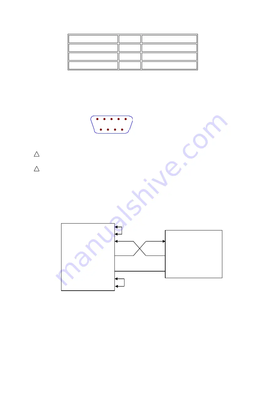
5.1.1.2 Communicating with a Computer
The tester is connected to the computer as shown:
As can be seen from the above figure, the pin definition of this tester is the same as that of the
9-core connector serial interface pinout used by IBM AT compatible machines.
Users can use
double-core shielded cable to make the three-wire connection cable according to the diagram (the
length should be less than 1.5m),
or purchase the serial interface cable between the computer and
the instrument from our company, or purchase a standard DB9 core cable (cross-line, null-modem).
When making the connection cable, be careful to short pin 4 and 6, and pin 7 and 8 on the 9-pin
computer connector as depicted above.
When communicating with the computer through the serial port, you should first set up the bus
mode of the tester. The operation sequence is as follows:
(View from outside)
1
2
3
4
5
6
7
8
9
DTR (4)
DSR (6)
RXD (2)
Computer
(Controller) TXD (3)
GND (5)
RTS (7)
CTS (8)
(2) RXD
(3) TXD ST9110
(5) GND


