◇
25
Note:
After modifying the data in the SETUP interface, switch the interface to TEST and the
instrument will save all data modifications. Please be careful not to shut down directly after
modifying the data to avoid data loss.
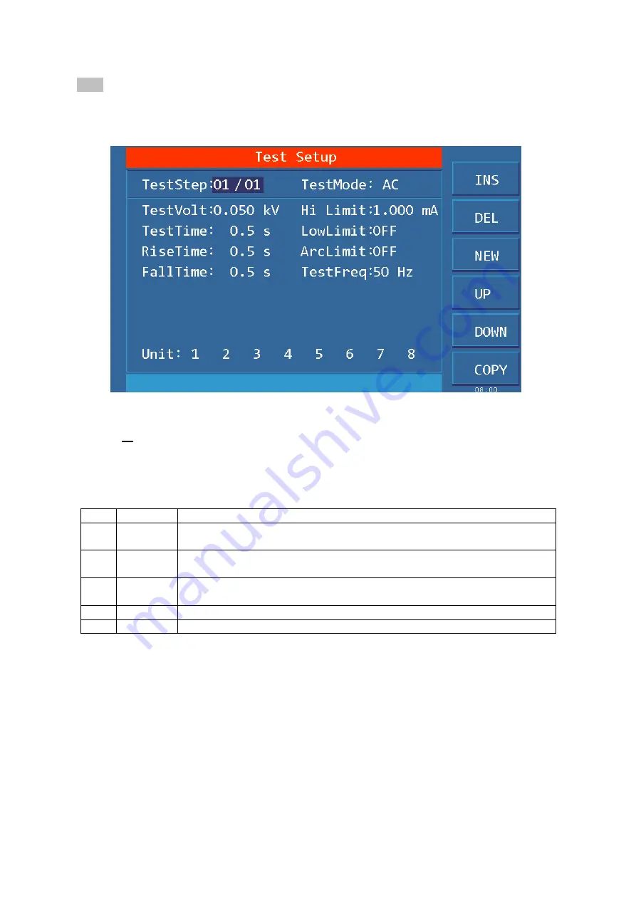
The interface is as follows:
Figure 4.2.2 AC SETUP Interface
Test file modification instructions
STEP
:
01/01
Step number of the current project/Total number of steps
The test step value is the serial number of the current test item in the test file, that is, the order in
which the test files are tested.
Project ID of the test file, the current parameter is nth step of the test file / total steps
Key
Fun.
Description
F1
INS
Add a new test step after the project, the test item for this step is the default.
The current project and the following projects will be moved one bit later.
F2
DEL
Delete current test step and test item. the next step project will move forward
one bit
F3
NEW
Create a new empty test file (STEP), the system will automatically create a
new default step and test project.
F4
+
Access the parameters of the previous step of the current display step
F5
-
Access the parameters of the step after the current display step
Test items: AC withstand voltage (AC) The test item of the current test procedure is AC
withstand voltage.
The test item of the current test procedure is AC withstand voltage, when the cursor is in this
position, you can switch to DC, IR, OS items via F1~F4.
For the parameter modification of the test project, see "4.3 Test Project Interface and
Parameter Description"
4.2.3
System Interface
The interface is as follows:
The system interface is to set some settings that are not related to the test project, but related to test


