2-10
UWP Series
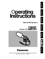
Spectrum analyzer
MM-SMA conversion connector and
SMA-BNC conversion connector
CN301
RF-131 board
Frequency
counter
Modulation
analyzer
CN301
RF-131 board
MM-SMA conversion connector and
SMA-BNC conversion connector
RF
IN
AF
OUT
Frequency check
Connections
(For connecting the DC power supply, refer to step
“3. Connecting the DC power supply” in Section 2-1-2.)
Procedure
n
Perform the checking with the AF INPUT connector short-
circuit.
1.
Set the modulation analyzer as below:
MEASUREMENT
: FM
MEASUREMENT RANGE :
±
40 kHz
HPF
: 4 kHz
LPF
: >20 kHz
DE EMPHASIS
: OFF
2.
Check that the frequency counter (resolution : 0.1 Hz
setting) reading is 32.000 kHz
±
1Hz.
Frequency deviation adjustment
Connections
(For connecting the DC power supply, refer to step
“3. Connecting the DC power supply” in Section 2-1-2.)
Procedure
1.
Connect the spectrum analyzer to the antenna terminal
(CN301/RF-131 board) via the MM-SMA conversion
connector and the SMA-BNC conversion connector.
2.
Set the spectrum analyzer as below:
CENTER FREQUENCY (fc)
U30 model
; 578.125 MHz
±
1 kHz
U42 model
; 650.125 MHz
±
1 kHz
CE62 model ; 810.000 MHz
±
1 kHz
CE67 model ; 850.000 MHz
±
1 kHz
KR model
; 746.125 MHz
±
1 kHz
REFERENCE LEVEL
: 20 dBm
FREQUENCY SPAN
: 200kHz (20 kHz/DIV)
RBW (resolution band width) : 3kHz
VBW (video band width)
: 1kHz
ATT
: 20 dB
3.
Adjust
1
RV511/RF-131 board (A side) so that level
between carrier frequency (frequency center level) on
spectrum analyzer and tone signal is within 29 dB
±
1 dB.
fc
32.000 kHz
29
±
1 dB
20 dBm
v:10 dB/div
H:20 MHz/div
Summary of Contents for UWP-V1
Page 4: ......
Page 20: ......
Page 94: ...3 6 UWP Series URX M2 3 2 3 URX M2 4 9 11 6 10 10 2 3 1 8 8 9 5 7 ...
Page 130: ......
Page 131: ...4 1 UWP Series 4 1 Section 4 Block Diagrams and Circuit Descriptions ...
Page 142: ......
Page 148: ......
Page 163: ......
Page 164: ...Printed in Japan Sony Corporation 2008 6 16 2008 UWP V1 V2 V6 X7 X8 U CE KR E 9 976 937 01 ...