2-10
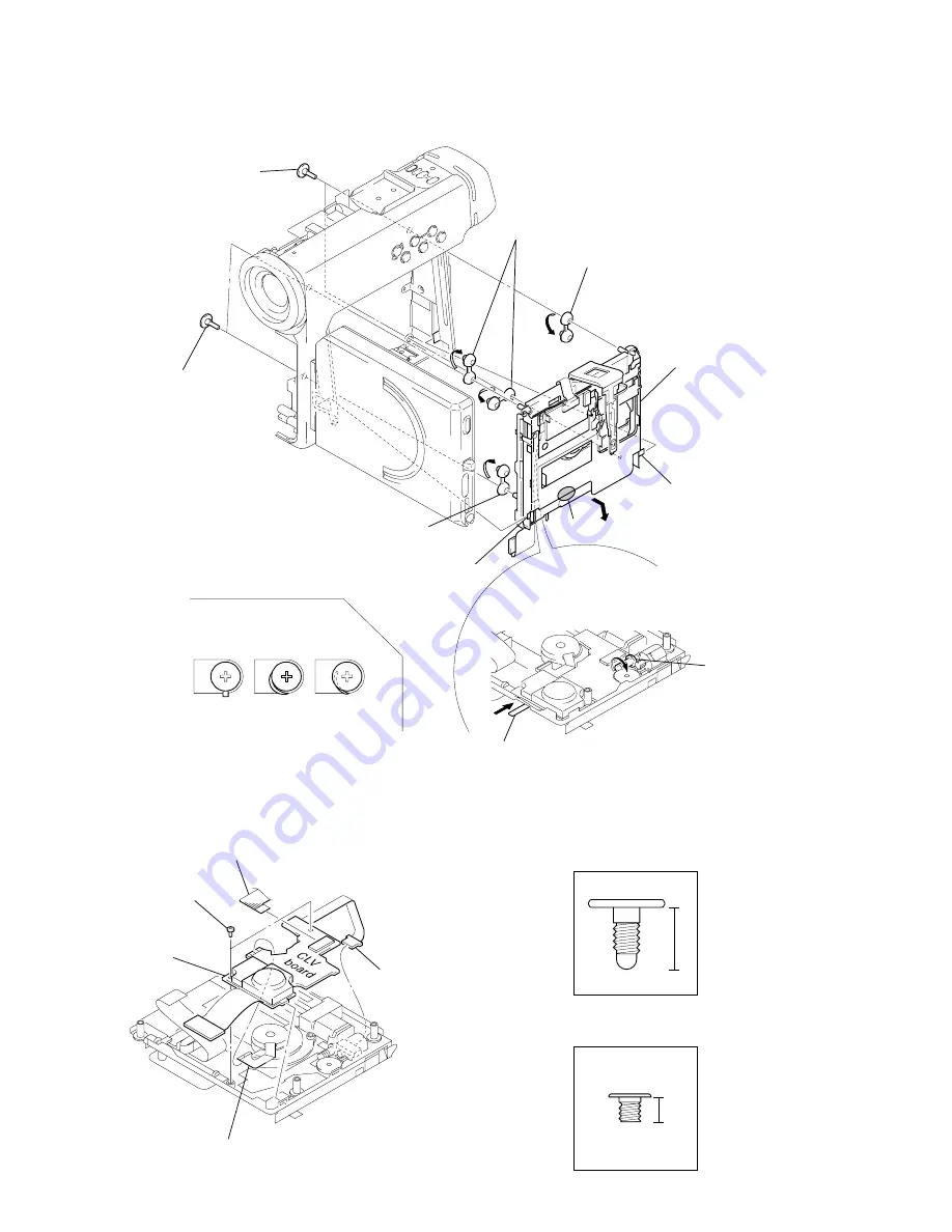
2-23. MECHANISM DECK
(MT-DCMM1-163)
2-24. CLV BOARD
3
Two screws (S13)
(damper)
OK
NG
NG
Note : When installing damper (MD),
put it together in the figure.
4
Damper (MD)
7
Claw
1
Rotate the worm gear in the direction
of the arrow
A
and move the torsion
spring (limitter) in the direction of the arrow
B
.
Worm gear
A
B
Torsion spring (limitter)
8
Claw
9
Hold the part maked
A
in the
figure trying not to touch either
over write head or OP.
Pulling the mechanism deck
(MT-DCMM1-163) toward you,
pull out it to the disc slot side.
6
Damper (MD)
5
Two dampers (MD)
2
Two screws (S13)
(damper)
A
4
Two screws (S14)
(M1.4)
2
Motor flexible board
(CN5801)
5
CLV board
1
Flexible board
(CN5902)
3
Remove the solders of the spindle
motor flexible board.
1.6
4
S13
S14
Summary of Contents for MDDISCAM DCM-M1
Page 5: ...1 1 SECTION 1 GENERAL This section is extracted from in struction manual 3 866 152 11 DCM M1 ...
Page 6: ...1 2 ...
Page 7: ...1 3 ...
Page 8: ...1 4 ...
Page 9: ...1 5 ...
Page 10: ...1 6 ...
Page 11: ...1 7 ...
Page 12: ...1 8 ...
Page 13: ...1 9 ...
Page 14: ...1 10 ...
Page 15: ...1 11 ...
Page 16: ...1 12 ...
Page 17: ...1 13 ...
Page 18: ...1 14 ...
Page 19: ...1 15 ...
Page 20: ...1 16 ...
Page 21: ...1 17 ...
Page 22: ...1 18 ...
Page 23: ...1 19 ...
Page 24: ...1 20 ...
Page 25: ...1 21 ...
Page 26: ...1 22 ...
Page 27: ...1 23 ...
Page 28: ...1 24 ...
Page 29: ...1 25 ...
Page 30: ...1 26 ...
Page 31: ...1 27 ...
Page 32: ...1 28 ...
Page 33: ...1 29 ...
Page 34: ...1 30 1 30 E ...
Page 47: ...2 13 MEMO ...
Page 69: ...DCM M1 4 5 4 6 4 7 4 8 4 1 FRAME SCHEMATIC DIAGRAM FRAME ...
Page 96: ...DCM M1 4 115 4 113 4 114 ETHER INTERFACE ETHER ...


