– 13 –
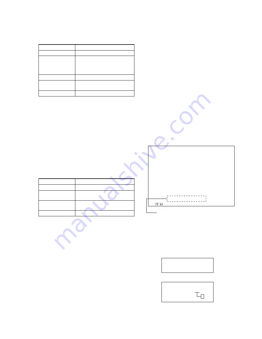
10. Backlight Consumed Current Adjustment
Set the brightness of backlight.
If deviated, the picture will be too dark or too bright.
Item number
3-01-09
Screen display
Color bar
Measurement point
+ probe: Adjusting monitor jig
I
pin
(BL+)
_ probe: Adjusting monitor jig
H
pin
(BL–)
Measuring instrument
Digital voltmeter
Adjustment data
B6
initial value
Adjustment value
A = 66.0
±
1.0 mV
Note:
Use AC adapter whenever performing this adjustment.
After turning on the power, wait for more than 30 seconds,
and then start the adjustment.
Adjusting method
1) Select the item number “3-01-09”.
2) Press the MENU key to display color bar on the LCD screen.
3) Using
e
and
E
keys, change the adjustment data so that po-
tential difference (A) between adjusting monitor jig
I
pin
(BL+) and
H
pin (BL–) satisfies the adjustment value.
4) Press
y
key to write the adjustment data.
5) Press the MENU key to return the LCD screen to the test mode
screen.
11. White Balance Adjustment
Adjust the white balance properly.
If deviated, the color reproducibility of LCD screen will be poor.
Item number
3-01-0A
Screen display
10-step gradation pattern (white/black)
Measurement point
Check on the LCD screen
Measuring instrument
Adjustment data
R data: 95
initial value
B data: 70
Adjustment value
LCD screen must not be colored
Note:
To switch between R data and B data, press
u
key.
After the adjustment finished, move to other item with R
data kept displayed.
Adjusting method
1) Select major item number “2” (EVF), and set the 10-step gra-
dation pattern (white/black).
2) Select the item number “3-01-0A”.
3) Set the adjustment data to initial value (R data:95, B data:70).
Note:
Each time the data is set, press
y
key to write data to
nonvolatile memory.
4) Press the DSPL key to display the 10-step gradation pattern
(white/black) on the LCD screen.
5) Check that the LCD screen is not colored.
If colored, change the adjustment data by using
e
and
E
keys
so that the LCD screen is not colored.
Note:
Each time the data is set, press
y
key to write data to
nonvolatile memory.
6) Press the DSPL key to return the LCD screen to the test mode
screen.
1-4.
Servo System Adjustment
1. Servo Auto Adjustment
The servo auto adjustment is executed automatically so that the
adjustment data of the servo system meets the optical pick-up block
in that set.
The servo auto adjustment checks the type of inserted disc and
executes automatically the adjustment that meets the inserted disc.
If the optical pick-up block or IC5405 on the Main board was
replaced, perform the servo auto adjustment with the following
three types of discs respectively.
• MD1 High reflectance pre-mastered disc (TDYS-1)
Part code: 4-963-646-01
• MD1 MO disc
Commercially available SONY MD1 MO disc (already recorded)
• MD2 MO disc
Commercially available SONY MD2 MO disc
Adjusting method
1) Select the item number “8-01-01”.
2) Insert the desired type of disc to be adjusted.
3) Press
y
key to execute the servo auto adjustment. (Auto ad-
justment will start and “Now Adjusting ...
ss
” will be dis-
played in the adjustment status display field.)
Note:
Place the set horizontally and perform adjustment un-
der stable condition.
Fig.7-1-18
4) At the completion of adjustment, the adjustment result will be
displayed in the adjustment status display field.
Note:
If an error occurs during adjustment, you can check
the item name where the error occurred. (Refer to
“Faulty item checking method”.)
Fig.7-1-19
5) Remove the disc inserted in step 2).
TEST MODE
Servo
made by MD dep.
I TRON
Ver.
s
.
sss
Drive
Ver.
s
.
sss
JAVA APP
Ver.
ssssssss
JAVA OS
Ver.
ssssssss
BOOT
Ver.
s
.
sss
I PL
Ver.
s
.
sss
RATE CTL
Ver.
s
.
sss
Item No.
All Adjust START
Now Adjusting . . .
ss
8–01–01
Servo Common
: 6C0 DATA : 00 00 00 30 00 00 00 00
Adjustment status display field
NG
OK!
NG.
ss
ss
• In case of successful adjustment
• In case of NG adjustment
A
Summary of Contents for MDDISCAM DCM-M1
Page 5: ...1 1 SECTION 1 GENERAL This section is extracted from in struction manual 3 866 152 11 DCM M1 ...
Page 6: ...1 2 ...
Page 7: ...1 3 ...
Page 8: ...1 4 ...
Page 9: ...1 5 ...
Page 10: ...1 6 ...
Page 11: ...1 7 ...
Page 12: ...1 8 ...
Page 13: ...1 9 ...
Page 14: ...1 10 ...
Page 15: ...1 11 ...
Page 16: ...1 12 ...
Page 17: ...1 13 ...
Page 18: ...1 14 ...
Page 19: ...1 15 ...
Page 20: ...1 16 ...
Page 21: ...1 17 ...
Page 22: ...1 18 ...
Page 23: ...1 19 ...
Page 24: ...1 20 ...
Page 25: ...1 21 ...
Page 26: ...1 22 ...
Page 27: ...1 23 ...
Page 28: ...1 24 ...
Page 29: ...1 25 ...
Page 30: ...1 26 ...
Page 31: ...1 27 ...
Page 32: ...1 28 ...
Page 33: ...1 29 ...
Page 34: ...1 30 1 30 E ...
Page 47: ...2 13 MEMO ...
Page 69: ...DCM M1 4 5 4 6 4 7 4 8 4 1 FRAME SCHEMATIC DIAGRAM FRAME ...
Page 96: ...DCM M1 4 115 4 113 4 114 ETHER INTERFACE ETHER ...


