– 23 –
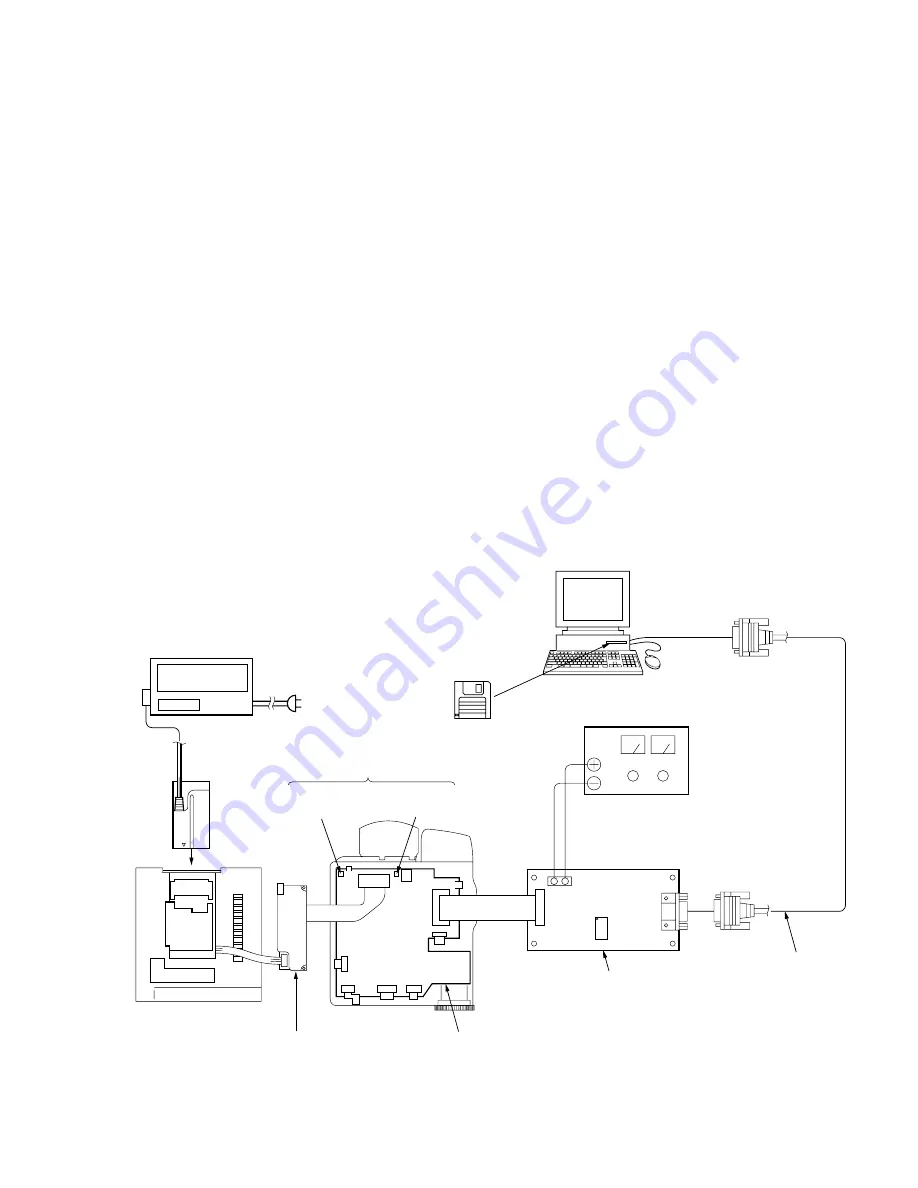
7-2. Firmware Data Writing Method
Write the data by the method given below, when the Main board
or the Flash Memory (IC8005) and MPEG Control (IC8501)
mounted on the MAIN board were replaced.
2-1.
Preparation
1. Measuring Equipment
To write the data, use measuring equipment listed below:
1) Personal computer (Windows95/98 installed)
2) Hyper Terminal (Communication software attached to the Win-
dows)
3) Firmware Writer Ether Flash BB(U)
Part code: J-2503-019-A
4) MPEG RATE CONTROL
Part code: J-2503-020-
s
5) RS-232C Cable D-Sub 9pin (Female) (Cross cable type)
6) Regulated power supply
7) AC Adaptor/Charger (AC-VQ800)
2. Connection
1) Disconnect the CN8801 of ETHER board from the CN8007
of MAIN board, and connect the Ether Flash BB instead.
Note:
Be careful of the connection direction when connecting
the Ether Flash BB.
2) Connect the CN7 of Ether Flash BB and the personal com-
puter with the RS-232C Cable (Cross cable type).
Fig.7-2-1
*1 Regulated power supply
(15 Vdc)
TP5002
GND
TP8047
TEST
Test pins
MAIN BOARD
POWER BOARD
Cabinet (R)
AC adaptor/charger
(AC-VQ800)
Ether Flash BB
RS-232C Cable
(Cross cable Type)
2 1
CN3
CN6
CN7
*1 Use the regulated power supply and
MPEG RATE CONTROL when
MPEG Control (IC8501) was replaced.
CN8007
Personal computer
to RS-232C
*1 MPEG RATE CONTROL
Summary of Contents for MDDISCAM DCM-M1
Page 5: ...1 1 SECTION 1 GENERAL This section is extracted from in struction manual 3 866 152 11 DCM M1 ...
Page 6: ...1 2 ...
Page 7: ...1 3 ...
Page 8: ...1 4 ...
Page 9: ...1 5 ...
Page 10: ...1 6 ...
Page 11: ...1 7 ...
Page 12: ...1 8 ...
Page 13: ...1 9 ...
Page 14: ...1 10 ...
Page 15: ...1 11 ...
Page 16: ...1 12 ...
Page 17: ...1 13 ...
Page 18: ...1 14 ...
Page 19: ...1 15 ...
Page 20: ...1 16 ...
Page 21: ...1 17 ...
Page 22: ...1 18 ...
Page 23: ...1 19 ...
Page 24: ...1 20 ...
Page 25: ...1 21 ...
Page 26: ...1 22 ...
Page 27: ...1 23 ...
Page 28: ...1 24 ...
Page 29: ...1 25 ...
Page 30: ...1 26 ...
Page 31: ...1 27 ...
Page 32: ...1 28 ...
Page 33: ...1 29 ...
Page 34: ...1 30 1 30 E ...
Page 47: ...2 13 MEMO ...
Page 69: ...DCM M1 4 5 4 6 4 7 4 8 4 1 FRAME SCHEMATIC DIAGRAM FRAME ...
Page 96: ...DCM M1 4 115 4 113 4 114 ETHER INTERFACE ETHER ...


