— 5 —
Lighting of All Fluorescent Indicator Tube Displays
and Key Check Mode
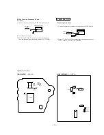
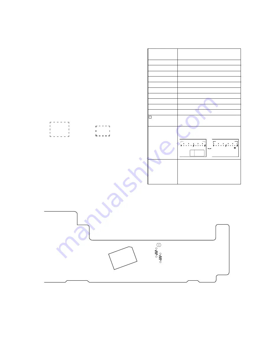
1. Connect the TEST2 (Short round) on the Main board with solder.
2. Connect the power plug to the outlet.
3. All the Fluorescent Indicator tube displays light up.
4. Press any button to enter the key check mode. In the key check
mode, each time a button is pressed, figures displayed on the Fluo-
rescent Indicator tube displays increase. However, figures will not
increase for buttons which have been pressed once.
The button number corresponding to the button pressed will also
be displayed. Button numbers are displayed only while the corre-
sponding buttons are pressed.
5. To exit the test mode, disconnect the power plug from the outlet.
7-segment display
[PANEL BOARD] (Conductor side)
Button Name
Button Number (Displayed only while a
button is pressed.)
KEY CONTROL
˜
KEY CONTROL
N
KEY CONTROL
n
KARAOKE STAR
DNR
§
OPEN/CLOSE
0
≠
)
±
SELECT
POWER
P
·
Figure 9
Figure 10
Figure 11
Figure 12
Figure 13
Figure 14
Figure 21
Figure 22
Figure 23
Figure 38 and adjustment LED (D403)
All Fluorescent Indicator tube
displays light up
Surround and other displays light up alter-
nately.
8
8
8
8
8
8
8
8
˜
IC402
TEST 2
R445
R424
n
Count up display
88
888888
Button number display
7 segments displays light up alternately
KEY CONTROL
RESUME
SUR
KARAOKE
THEATER
PON
KEY CONTROL
AUTO
MUSIC
STAR
n
Summary of Contents for MCE-K700
Page 8: ... 8 ...
Page 9: ... 9 ...
Page 10: ... 10 ...
Page 11: ... 11 ...
Page 12: ... 12 ...
Page 13: ... 13 ...
Page 14: ... 14 ...
Page 15: ... 15 ...
Page 16: ... 16 ...
Page 21: ......
Page 22: ......
Page 23: ......
Page 24: ......
Page 25: ......
Page 26: ......
Page 27: ......


