— 4 —
SECTION 2
TEST MODE
VIDEO CD COLOR-BARS MODE
On this mode, the data of the color-bars signal as a picture signal and
the 1kHz sine wave signal as a sound signal are output by the mecha-
nism control microcomputer (IC501) for video CD signal check. When
measurement of the voltage and waveform on the VIDEO board,
perform it in this mode.
For refernce, the color-bars signal can be observed at J101 (VIDEO
OUT) and the sound signal can be observed at J102 (AUDIO OUT)
using an oscilloscope.
1. Turn the power on.
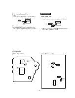
2. Connect the SL501 (C BAR) on the VIDEO board with solder.
3. After measuring, remove the soldering installed.
E-F BALANCE MODE
• Refer to SECTION 5 ELECTRICAL ADJUSTMENTS page 15.
1. Turn the power on.
2. Connect the SL502 and SL503 on the VIDEO board with solder.
3. Press the
·
button in playback.
4. Every pressing the KARAOKE STAR button, the tracking servo
and the sledding servo are turned on or off.
5. When the servo is OFF, the counter on front panel will not be
changed.
6. After measuring, remove the soldering installed.
[VIDEO BOARD] — SIDE B —
Summary of Contents for MCE-K700
Page 8: ... 8 ...
Page 9: ... 9 ...
Page 10: ... 10 ...
Page 11: ... 11 ...
Page 12: ... 12 ...
Page 13: ... 13 ...
Page 14: ... 14 ...
Page 15: ... 15 ...
Page 16: ... 16 ...
Page 21: ......
Page 22: ......
Page 23: ......
Page 24: ......
Page 25: ......
Page 26: ......
Page 27: ......


