background image

Chapter 1
Overview

HDS-7100 System Introduction ............................................... 1-2

System Configuration ......................................................... 1-2
Operation Software ............................................................. 1-3
Features ............................................................................... 1-5

Channel Assignments ............................................................... 1-7
Starting Up and Powering Off ................................................. 1-8
Examples of DME Effects ........................................................ 1-9

Three-Dimensional Transformations .................................. 1-9
Background and Edge Effects .......................................... 1-10
Freeze and Afterimage Effects ......................................... 1-10
Overall Image Effects ....................................................... 1-11
Video Signal Effects ......................................................... 1-11
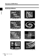
Nonlinear Effects .............................................................. 1-12

Summary of Contents for HDS-7100

Page 1: ...Operation Software HZS 7060 User s Guide HD Digital Video Switcher HDS 7100 Volume 2 1st Edition Software Version 1 00 and Later English ...

Page 2: ...F MERCHANTABILITY OR FITNESS FOR ANY PARTICULAR PURPOSE WITH REGARD TO THIS MANUAL THE SOFTWARE OR SUCH OTHER INFORMATION IN NO EVENT SHALL SONY CORPORATION BE LIABLE FOR ANY INCIDENTAL CONSEQUENTIAL OR SPECIAL DAMAGES WHETHER BASED ON TORT CONTRACT OR OTHERWISE ARISING OUT OF OR IN CONNECTION WITH THIS MANUAL THE SOFTWARE OR OTHER INFORMATION CONTAINED HEREIN OR THE USE THEREOF Sony Corporation r...

Page 3: ...ame and Target Coordinate Frame 3 4 Three Dimensional Coordinates 3 5 Specializing the Effect of the Trackball and Z Ring 3 7 Moving the Image 3 9 Moving in the Source Coordinate Frame 3 9 Moving in the Target Coordinate Frame 3 11 Rotating the Image 3 13 Rotating in the Source Coordinate Frame 3 13 Rotating in the Target Coordinate Frame 3 15 Moving the Axes of Rotation 3 17 Moving the Axes of Ro...

Page 4: ...een Operations 4 5 Initial Screen 4 8 Example Screen 4 8 Basic Operations in the Initial Screen 4 8 Top Menu Screens 4 9 Example Screen 4 9 Basic Operations in a Top Menu 4 10 Parameter Setting Screens 4 11 Example Screen 4 11 Basic Operations in a Parameter Setting Screen 4 12 Chapter 5 Special Effects Operations Quick Enabler 5 3 QUICK ENABLER Settings 1 5 3 Auto Cube Function 5 5 Number of Chan...

Page 5: ... 39 POSTER Posterization NEGA Negative Settings 41 5 40 SEPIA MONO Monochrome Settings 42 5 42 CONTRAST Settings 43 5 43 MOSAIC Settings 44 5 45 MASK Settings 45 5 46 Nonlinear Effects 5 48 Effect Selection 100 5 48 WAVE Settings 101 5 51 MOSAIC GLASS Settings 102 5 56 FLAG Settings 103 5 56 RIPPLE Settings 104 5 57 RINGS Settings 105 5 59 BROKEN GLASS Settings 106 5 60 FLYING BARS Settings 107 5 ...

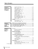
Page 6: ...inued Chapter 6 Input Output Signal Operations DME Selection and Input Output Signals 6 2 Selecting Input Output Operations 50 6 3 Video Signal and Key Signal Settings 51 6 4 Inverting the Input Signal 55 6 6 Chapter 7 Keyframe Effects Overview 7 2 Keyframes and Effects 7 2 Basic Procedure 7 3 Registers and Channels 7 4 Accessing Registers 7 4 Channel Selection 7 6 Generating and Editing Keyframes...

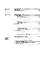
Page 7: ... Overview 8 27 Snapshot Operations 75 8 28 Changing Snapshot Names 76 8 32 Channel to Channel Snapshot Copy 79 8 33 Memory Recall 8 34 Memory Recall Selection 500 8 34 Memory Recall Panel Operations 501 8 35 Memory Recall Setup Operations 502 8 37 Chapter 9 Status Displays Selecting Status Display 600 9 2 Three Dimensional Transformation Status Display 601 9 3 Keyframe Three Dimensional Transforma...

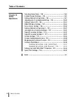
Page 8: ...ed to Operation 2 707 10 19 Automatic Key Selection Settings 713 10 21 Signal Processing Settings 716 10 23 Signal Processing Settings 2 717 10 25 System Settings 721 10 26 System Configuration Screen 722 10 28 Displaying the Software Version 723 10 29 Software Installation 10 30 Installing the Software in the Control Panel 10 31 Installing the Software in the Processor 724 10 32 Settings for the ...

Page 9: ...ftware 1 3 Features 1 5 Channel Assignments 1 7 Starting Up and Powering Off 1 8 Examples of DME Effects 1 9 Three Dimensional Transformations 1 9 Background and Edge Effects 1 10 Freeze and Afterimage Effects 1 10 Overall Image Effects 1 11 Video Signal Effects 1 11 Nonlinear Effects 1 12 ...

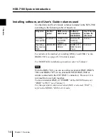
Page 10: ... System Configuration The following figure shows an example configuration of an HDS 7100 system HDS 7100 System Introduction BKDS 2010 Switcher Control Panel For details of operations from this panel refer to Volume 1 This manual Volume 2 covers operations from this panel HKDS 7695 Power Supply Unit Internal DME option HKDS 7061 Video Modifier Board HKDS 7071 Digital Multi Effects Board HDS 7100 H...

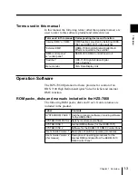
Page 11: ...ded by installing HKDS 7061 and HKDS 7071 in the switcher External DME HDME 7000 High Definition Digital Multi Effects connected to the switcher DME control panel or control panel BKDM 3010 DME Control Panel Unit Switcher HDS 7100 High Definition Digital Video Switcher Label Contents SYSTEM ROM PACK 1 Switcher processor software including software for the HKDS 7061 SYSTEM ROM PACK 2 Switcher contr...

Page 12: ...1 or an external DME HDME 7000 or similar connected to the EXT DME 1 connector However it is not possible to use both together To use an internal DME in PERIPH of the SETUP menu set DME to INT see Volume 1 For the operations when an external DME is selected EXT refer to the HZDM 7020 User s Guide Objective Control panel ROM packs or disks used Software installation destination User s Guide volume ...

Page 13: ...a video image Background coloring and edge effects Freeze and strobe effects using recursive memory functions and afterimage effects Overall image effects multi move and defocusing for example Video and key signal transformations negative image mosaic effects etc Various nonlinear effects waves page turns and so forth Lighting effects Keyframe effects You can save DME image states and special effe...

Page 14: ...any menu directly from menus in the other menu groups by entering its page number from the numeric keypad Editor interfaces It is possible to use an editing control unit such as the BVE 2000 or BVE 9100 connected to either the Sony 9 pin remote interface or the GPI interface for execution of key frame and other effects Note The photographs and figures of screen examples in this User s Guide illust...

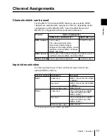
Page 15: ...t External video input 1 Video input Key input External video input 1 Bus used DME V Press the VM V DME V button DME K Press the VM K DME K button DME VM EXT VM V Hold down the SHIFT button and press the VM V DME V button VM K Hold down the SHIFT button and press the VM K DME K button DME VM EXT Channel HKDS 7061 and HKDS 7071 HKDS 7061 only DME channel 1 Can be used This channel provides three di...

Page 16: ...stem regardless of the current display on the menu monitor Note Do not power the unit off during any of the following operations While a floppy disk is being accessed see Floppy Disk Operations 77 on page 8 15 This may cause files on the floppy disk or backup copies of data in the processor contents of effect registers or snapshot registers to be corrupted During installation of the software see I...

Page 17: ...ch the corresponding procedures are described The following screen examples illustrate the case where the aspect ratio is set to the 4 3 mode When the 16 9 mode is selected the screen aspect ratio is 16 9 See page 10 27 Three DimensionalTransformations Displacement in 3 D space page 3 9 Rotation in 3 D space page 3 13 Perspective deformation page 3 26 Examples of DME Effects k k k k k k ...

Page 18: ...r 1 Overview 1 Overview Background and Edge Effects BORDER page 5 13 CROP page 5 16 DROP SHADOW page 5 18 Freeze and Afterimage Effects MOTION DECAY page 5 24 TRAIL page 5 27 WIND page 5 29 Examples of DME Effects ...

Page 19: ...Chapter 1 Overview 1 11 1 Overview Overall Image Effects MULTI MOVE page 5 35 DEFOCUS page 5 36 Video Signal Effects k NEGA page 5 40 MOSAIC page 5 45 ...

Page 20: ... 1 Overview 1 Overview Nonlinear Effects WAVE page 5 51 FLAG page 5 56 RIPPLE page 5 57 RINGS page 5 59 BROKEN GLASS page 5 60 FLYING BARS page 5 61 SPLIT page 5 62 CHARACTER TRAIL page 5 65 Examples of DME Effects ...

Page 21: ...Chapter 1 Overview 1 13 1 Overview MIRROR page 5 66 LENS page 5 67 CIRCLE page 5 68 PANORAMA page 5 69 PAGETURN page 5 70 CYLINDER page 5 73 SPHERE page 5 75 ...

Page 22: ...r 2 Location and Function of Parts Control Panel 2 2 Transformation Operation Section 2 3 Keyframe Operation Section 2 6 Channel Selection Section 2 10 Menu Operation Section 2 12 Numeric Keypad Section 2 14 ...

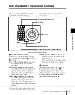
Page 23: ...eration section page 2 3 Numeric keypad section page 2 14 SWITCH WINDW F1 F2 F3 F4 F5 F6 F7 F8 EXIT LAST MENU FREZE 10 BKGD EDGE 20 FREZE RECUR 30 PIX MOD 40 VIDEO MOD 50 IN OUT 60 PATH CTRL 70 EFF UTLTY 100 MON LINEAR 200 GRAPH 300 LIGHT EFF 400 500 SHOT BOX 600 STATS 700 SET DIAG GLBL CH1 CH2 KF EDIT ENABL RUN REW REVS RECAL EFF STORE EFF CLR WORK BUFF STP NEXT KF UNDEL UNDO BEFR INSRT TC GOTO K...

Page 24: ...the source coordinate frame that is the coordinates based on the video image itself 1 TRGT target button Allocates the trackball and Z ring to transformation operation in the target coordinate frame that is the coordinates based on the output video space on the main monitor 1 CURSR cursor button Allocates the trackball to cursor movement on the menu screens 1 This also allocates the Z ring to adju...

Page 25: ...hen the SRCE button is lit pressing this button while holding down the SHIFT button in the keyframe operation section displays the X Y and RATE parameters in the three dimensional parameter display section of the menu screen You can then change the image sizes in the x and y directions separately by using the trackball and adjust the aspect ratio using the Z ring When the TRGT button is lit the tr...

Page 26: ...ion X Y Z buttons Use these buttons to restrict the axes affected by movement of the trackball and Z ring Additionally when one of these buttons is lit the numeric keypad can be used to input coordinate data for that axis CTR center button Pressing this button changes the current data values for the trackball or Z ring positions to closest system specified values i e provides a detent function Imm...

Page 27: ...stored in that register Entering a period in place of the number selects the next vacant register after the currently recalled register Pressing this button then entering 0 returns to the state before recalling the current effect that is to the state before carrying out the edit STORE EFF effect button Pressing this button then entering a register number saves a keyframe effect in the correspondin...

Page 28: ...lled effect to the initial keyframe unless the REVS button is lit in which case it winds forward to the last keyframe REVS reverse button When this button is lit you can execute the effect in the reverse direction using the RUN button STP stop NEXT KF keyframe button When this button is lit pressing the RUN button executes the effect from the current position to the next keyframe 4Duration setting...

Page 29: ...ntaneous state of the effect While the effect is positioned on a keyframe this corresponds to the contents of the keyframe and while the effect is between keyframes to a result of interpolation Pressing this button while holding down the SHIFT button 5 in the keyframe operation section resets all parameter values in the active window displayed on the menu screen to their default values UNDEL UNDO ...

Page 30: ...s button on its own inserts the new keyframe after the current keyframe if the effect is currently stopped on a keyframe Pressing this button while holding down the SHIFT button 5 inserts the new keyframe before the current keyframe If the effect is stopped between keyframes the new keyframe is inserted at the current position 8Floppy disk drive This accepts a 3 5 inch floppy disk for loading or s...

Page 31: ... channel selection section turning them on selects the active channel or channels to which menu operations and control panel operations apply More than one channel can be active simultaneously Channel 1 and the global channel GLBL global button This selects the global channel This channel is used for example when adding another movement on top of the image movements set up for channel 1 See figure...

Page 32: ...erence channel Lit red This channel is active but is not the reference channel The buttons for all active channels other than the reference channel are always lit red To make one channel only active press the corresponding channel button The button lights green and the channel is then the reference channel To make more than one channel active hold down the button for the channel you wish to make t...

Page 33: ...t menu operations on the menu monitor 1SWTCH WINDW switch window button Pressing this button switches the active window on the menu monitor between the upper and lower windows All settings take effect in the active window 2 Function keys F1 to F8 The function keys are used to make on off selections select operations and change menus in the active window The functions are displayed in corresponding...

Page 34: ... It is also possible to set up the system so that you can select a desired top menu by pressing the corresponding top menu selection button only once see page 10 8 5Jandj buttons These buttons are used to select the line of a menu screen on which items are to be selected or parameters adjusted 6LAST MENU button Pressing this button recalls the menu displayed immediately previously in the active wi...

Page 35: ...ts default value 2PAGE button Pressing this button allows a menu page number to be entered from the numeric keypad This switches the active window to the menu with the corresponding page number 3Numeric keypad 0 to 9 buttons Used to enter digits button Used to toggle the sign of an entered value CLR clear button Press this button once to clear the entered value and allow the value to be entered ag...

Page 36: ...ent values being added ENTER button Confirms an entered numeric value Because of the effects of rounding in numerical computations the value displayed may differ slightly from the entered value When there is a pop up window on the screen pressing this button selects OK decimal point button Enters a decimal point In a time code value this is also used as the separator between minutes seconds and fr...

Page 37: ...ordinate Frame 3 15 Moving the Axes of Rotation 3 17 Moving the Axes of Rotation in the Source Coordinate Frame 3 17 Moving the Axes of Rotation in the Target Coordinate Frame 3 19 Magnifying or Shrinking the Image 3 21 Magnifying or Shrinking in the Source Coordinate Frame 3 21 Magnifying or Shrinking in the Target Coordinate Frame 3 22 Changing the Skew Aspect Ratio or Perspective of the Image 3...

Page 38: ...se the following procedure 1 Use the channel selection section to select the channel to which the transformation is to apply 2 Press one of the following buttons in the function allocation section turning it on to select the coordinate frame for the transformation See page 3 4 Source coordinate frame SRCE button Target coordinate frame TRGT button This assigns the trackball and Z ring to transform...

Page 39: ...rspective ASP SKEW PERS button page 3 24 5 Operate the trackball or Z ring to make the transformation as follows To make an arbitrary two dimensional movement use the trackball To move along the x axis only move the trackball to left or right To move along the y axis only move the trackball up or down To move along the z axis turn the Z ring To continue a transformation at a constant speed hold do...

Page 40: ...take place in either the source coordinate frame or the target coordinate frame The source coordinate frame is with respect to the original input video image That is as the video image is rotated for example the coordinates rotate with respect to the output video space The target coordinate frame is with respect to the output video space These coordinates are thus fixed independently of manipulati...

Page 41: ...espectively over the area of the image In the target coordinate frame the origin is at the center of the output video space and the x and y coordinates range from 4 to 4 and 2 25 to 2 25 respectively over the area of the output video space When using a 4 3 aspect ratio screen however the ranges are x from 4 to 4 and y from 3 to 3 The limits for the x y and z coordinates are from 999 to 999 X y and...

Page 42: ...ue for the selected axis from the numeric keypad You can enter a value with up to four decimal places It is also possible to enter a difference from the current value 3 If you entered the new value press the ENTER button If you entered a difference press the TRIM button This changes the coordinate value and the output video changes accordingly Detent positions and resetting The three dimensional a...

Page 43: ...s are reset to zeros Specializing the Effect of the Trackball and Z Ring You can restrict the axes controlled by the trackball and Z ring or constrain the way in which the image moves Restricting a transformation to particular axes To restrict the effect of the trackball and Z ring on the transformation to particular axes press one or two of the X Y and Z buttons turning them on Restricting a tran...

Page 44: ...e VELO HOLD button while turning the trackball or Z ring The speed is detected and then as long as you hold this button down the image continues to change at the same speed even after releasing the trackball or Z ring In the TRACK BALL menu page 10 10 you can select whether the automatic speed is the same as the detected speed or slower than the detected speed Other trackball and Z ring settings I...

Page 45: ...n press the SRCE button turning it on 2 In the transformation mode selection section press the LOC XYZ button turning it on If you wish to move the image in the x and y directions only pressing the LOC SIZE button has the same effect 3 Move the trackball to move the image in the x and y directions Turn the Z ring to move the image in the z direction Moving along the x axis X Y Z RUN CTRL CURSR TRG...

Page 46: ... SRCE ASP SKEW PERS LOC SIZE LOC XYZ VELO HOLD CTR ORTHG AXIS LOC ROT SEL FINE Control panel operation Video change Moving along the z axis X Y Z RUN CTRL CURSR TRGT SRCE ASP SKEW PERS LOC SIZE LOC XYZ VELO HOLD CTR ORTHG AXIS LOC ROT SEL FINE Control panel operation Video change LOC XYZ button or LOC SIZE button SRCE button LOC XYZ button SRCE button ...

Page 47: ...2 In the transformation mode selection section press the LOC XYZ button turning it on If you wish to move the image in the x and y directions only pressing the LOC SIZE button has the same effect 3 Move the trackball to move the image in the x and y directions Turn the Z ring to move the image in the z direction Moving along the x axis X Y Z RUN CTRL CURSR TRGT SRCE ASP SKEW PERS LOC SIZE LOC XYZ ...

Page 48: ...SIZE LOC XYZ VELO HOLD CTR ORTHG AXIS LOC ROT SEL FINE Control panel operation Video change Moving along the z axis X Y Z RUN CTRL CURSR TRGT SRCE ASP SKEW PERS LOC SIZE LOC XYZ VELO HOLD CTR ORTHG AXIS LOC ROT SEL FINE Control panel operation Video change TRGT button LOC XYZ button or LOC SIZE button TRGT button LOC XYZ button Main monitor Moving the Image ...

Page 49: ...edure To rotate the image in the source coordinate frame use the following procedure in the transformation operation section 1 In the function allocation section press the SRCE button turning it on 2 In the transformation mode selection section press the ROT button turning it on 3 Move the trackball to rotate the image about the x and y axes Turn the Z ring to rotate the image about the z axis Rot...

Page 50: ... RUN CTRL CURSR TRGT SRCE ASP SKEW PERS LOC SIZE LOC XYZ VELO HOLD CTR AXIS LOC ROT SEL FINE Control panel operation Video change Rotating about the z axis X Y Z RUN CTRL CURSR TRGT SRCE ASP SKEW PERS LOC SIZE LOC XYZ VELO HOLD CTR ORTHG AXIS LOC ROT SEL FINE X Y Z RUN CTRL CURSR TRGT SRCE ASP SKEW PERS LOC SIZE LOC XYZ VELO HOLD CTR AXIS LOC ROT SEL FINE Control panel operation Video change SRCE ...

Page 51: ...ode selection section press the ROT button turning it on 3 Move the trackball to rotate the image about the x and y axes Turn the Z ring to rotate the image about the z axis Rotating about the y axis X Y Z RUN CTRL CURSR TRGT SRCE ASP SKEW PERS LOC SIZE LOC XYZ VELO HOLD CTR ORTHG AXIS LOC ROT SEL FINE Control panel operation Video change Rotating about the x axis X Y Z RUN CTRL CURSR TRGT SRCE AS...

Page 52: ...bout the z axis X Y Z RUN CTRL CURSR TRGT SRCE ASP SKEW PERS LOC SIZE LOC XYZ VELO HOLD CTR ORTHG AXIS LOC ROT SEL FINE X Y Z RUN CTRL CURSR TRGT SRCE ASP SKEW PERS LOC SIZE LOC XYZ VELO HOLD CTR AXIS LOC ROT SEL FINE Control panel operation Video change TRGT button ROT button Rotating the Image ...

Page 53: ...llocation section press the SRCE button turning it on 2 In the transformation mode selection section press the AXIS LOC button turning it on 3 Move the trackball to move the axes of rotation in the x and y directions Turn the Z ring to move the axes of rotation in the z direction Moving along the x axis X Y Z RUN CTRL CURSR TRGT SRCE ASP SKEW PERS LOC SIZE LOC XYZ VELO HOLD CTR ORTHG AXIS LOC ROT ...

Page 54: ...rol panel operation Positional change Moving along the z axis X Y Z RUN CTRL CURSR TRGT SRCE ASP SKEW PERS LOC SIZE LOC XYZ VELO HOLD CTR ORTHG AXIS LOC ROT SEL FINE X Y Z RUN CTRL CURSR TRGT SRCE ASP SKEW PERS LOC SIZE LOC XYZ VELO HOLD CTR AXIS LOC ROT SEL FINE Y X Y X Control panel operation Positional change Note After changing the LOC SIZE and ROT settings in the target coordinate frame if yo...

Page 55: ...e function allocation section press the TRGT button turning it on 2 In the transformation mode selection section press the AXIS LOC button turning it on 3 Move the trackball to move the axes of rotation in the x and y directions Turn the Z ring to move the axes of rotation in the z direction Moving along the x axis X Y Z RUN CTRL CURSR TRGT SRCE ASP SKEW PERS LOC SIZE LOC XYZ VELO HOLD CTR ORTHG A...

Page 56: ... XYZ VELO HOLD CTR ORTHG AXIS LOC ROT SEL FINE Y X X Control panel operation Positional change Moving along the z axis Control panel operation Positional change TRGT button AXIS LOC button Main Monitor X Y Z RUN CTRL CURSR TRGT SRCE ASP SKEW PERS LOC SIZE LOC XYZ VELO HOLD CTR ORTHG AXIS LOC ROT SEL FINE Y Y Z TRGT button AXIS LOC button Moving the Axes of Rotation ...

Page 57: ...rce coordinate frame use the following procedure in the transformation operation section 1 In the function allocation section press the SRCE button turning it on 2 In the transformation mode selection section press the LOC SIZE button turning it on 3 Turn the Z ring clockwise to magnify or counterclockwise to shrink the image X Y Z RUN CTRL CURSR TRGT SRCE ASP SKEW PERS LOC SIZE LOC XYZ VELO HOLD ...

Page 58: ...ransformation operation section 1 In the function allocation section press the TRGT button turning it on 2 In the transformation mode selection section press the LOC SIZE button turning it on 3 Turn the Z ring clockwise to magnify or counterclockwise to shrink the image X Y Z RUN CTRL CURSR TRGT SRCE ASP SKEW PERS LOC SIZE LOC XYZ VELO HOLD CTR ORTHG AXIS LOC ROT SEL FINE Control panel operation V...

Page 59: ...ction press the ASP SKEW PERS button turning it on 3 Move the trackball in the x and y directions to change the skew of the image Turn the Z ring to change the aspect ratio Note It is also possible to set up the trackball so that when the ASP SKEW PERS button is lit movement in the x or y direction only changes the aspect ratio If with this setting made you wish to change the skew using the trackb...

Page 60: ... LOC SIZE LOC XYZ VELO HOLD CTR ORTHG AXIS LOC ROT SEL FINE Control panel operation Video change movement in the y direction also possible Changing the aspect ratio changing x and y directions together X Y Z RUN CTRL CURSR TRGT SRCE ASP SKEW PERS LOC SIZE LOC XYZ VELO HOLD CTR ORTHG AXIS LOC ROT SEL FINE Control panel operation Video change SRCE button ASP SKEW PERS button SRCE button ASP SKEW PER...

Page 61: ...S button turning it on while holding down the SHIFT button in the key frame operation section For details see the TRACK BALL menu on page 10 10 Even when you make this XY ASPECT setting it is still possible also to use the Z ring to change the aspect ratio X Y Z RUN CTRL CURSR TRGT SRCE ASP SKEW PERS LOC SIZE LOC XYZ VELO HOLD CTR ORTHG AXIS LOC ROT SEL FINE Control panel operation Video change X ...

Page 62: ...e following procedure in the transformation operation section 1 In the function allocation section press the TRGT button turning it on 2 In the transformation mode selection section press the ASP SKEW PERS button turning it on 3 Use the trackball to move the viewpoint in the x and y directions Turn the Z ring to change the perspective in the z direction Moving the viewpoint in the x direction X Y ...

Page 63: ...EW PERS LOC SIZE LOC XYZ VELO HOLD CTR ORTHG AXIS LOC ROT SEL FINE Control panel operation Change in viewpoint position Changing the perspective X Y Z RUN CTRL CURSR TRGT SRCE ASP SKEW PERS LOC SIZE LOC XYZ VELO HOLD CTR ORTHG AXIS LOC ROT SEL FINE Control panel operation Change in the perspective TRGT button ASP SKEW PERS button TRGT button ASP SKEW PERS button ...

Page 64: ...the function allocation section turning it on To set the number of rotations in the target coordinate frame press the TRGT button in the function allocation section turning it on 2 Carry out either of the following operations Hold down the SHIFT button in the key frame operation section and press the ROT button in the transformation mode selection section In the 3D TRANSFORM menu menu page 601 pre...

Page 65: ...4 Basic Menu Screen Operations 4 5 Initial Screen 4 8 Example Screen 4 8 Basic Operations in the Initial Screen 4 8 Top Menu Screens 4 9 Example Screen 4 9 Basic Operations in a Top Menu 4 10 Parameter Setting Screens 4 11 Example Screen 4 11 Basic Operations in a Parameter Setting Screen 4 12 ...

Page 66: ...O 54 BACK KEY 55 INPUT INVERT 57 EXT VIDEO IN OUT 60 PATH 61 PATH ALL 62 PATH TRANSFORM 62 1 PATH TRANS 1 62 2 PATH TRANS 2 62 3 PATH TRANS 3 63 PATH BKGD EDGE 64 PATH FREEZE RECUR 65 PATH PICTURE MODIFY 66 PATH VIDEO MODIFY 67 PATH INPUT OUTPUT 68 PATH MATTE 70 EFFECT UTILITY 71 EFFECT RUN MODE 72 REGISTER 73 REGISTER NAME 74 CHANNEL COPY 75 SNAPSHOT 75 1 SNAPSHOT ATTRIBUTE 76 SNAPSHOT NAME 77 DI...

Page 67: ...2 721 SYSTEM 722 SYSTEM CONFIGURATION 723 VERSION 724 INSTALL 725 DME LINK 726 SPARE PORT 100 NONLINEAR 101 WAVE 101 1 WAVE FORM 101 2 WAVE RANGE 102 MOSAIC GLASS 102 1 MOSAIC GLASS FORM 102 2 MOSAIC GLASS RANGE 103 FLAG 103 1 FLAG FORM 103 2 FLAG RANGE 104 RIPPLE 104 1 RIPPLE FORM 104 2 RIPPLE RANGE 105 RINGS 106 BROKEN GLASS 107 FLYING BARS 108 SPLIT 109 SPLIT SLIDE 110 CHARACTER TRAIL 111 MIRRO...

Page 68: ...NE CH 1 78 EFFECT78 2 6 00 12 34 F INS APEND DEL MOD STOP NEXT KF REV EXPAND GBL Lum Sat Hue BORDER Width All Separate Width Density SOURCE FLAT EDGE SOFT H Left Top Lum Innr 0 15 0 15 12 34 22 22 0 15 0 15 Bttm Sat Outr 44 44 99 99 33 33 All 0 V Rght E G 1 2 R 00 12 00 3 6 78 EFFECT78 KFDUR PAGE 12 TRGT LOC XYG X 12 1116 Y 1 0002 Z BORDER FLAT COLOR HUE ROT EXT VIDEO BORDER SOFT 13 CROP S CH 2 CH...

Page 69: ...movement 2 Move the trackball to position the cursor over the required item 3 Press the SEL FINE button Using the mouse If you have a mouse connected to the SPARE connector on the rear of the control panel you can use the mouse to position the cursor and click with the left mouse button Switching active windows The menu screen has two windows arranged one above the other the active window that is ...

Page 70: ...tion is enabled or on the indicator turns red Bringing up a menu in the active window You can use any of the following techniques to bring up a required menu in the active window To access a menu shown in one of the soft key indications click on the box or press the corresponding function key Press a button in the top menu selection section Press the PAGE button in the numeric keypad section then ...

Page 71: ...in the active window TRGT LOC XYZ X 12 1116 Y 1 0002 Z 90 1118 To change a coordinate value either carry out a transformation using the trackball and Z ring or press one of the X Y and Z buttons and enter the value from the numeric keypad For details see Chapter 3 Three Dimensional Transformations Selected path type Selected mode Selected coordinate frame SRCE TRGT x y and z coordinate values ...

Page 72: ...c Operations in the Initial Screen Accessing a top menu To access one of the top menus shown either click on the screen indication or press the corresponding button in the top menu selection section Initial Screen Top menus HIGH DEFINITION DIGITAL MULTI EFFECTS 1999 Sony Corporation 0 TOP MENU LIST PAGE 0 10 BKGD EDGE 100 NON LINEAR 20 FREEZE RECUR 30 PICTURE MODIFY 300 LIGHT EFFECT 40 VIDEO MODIF...

Page 73: ...shown below appears in the active window Example top menu screen BKGD EDGE menu Top Menu Screens Indicates whether the image displayed in the monitor is front F or back B video Page number and menu title Submenus selectable directly from the top menu Parameter reset 10 BKGD EDGE BKGD BORDER CROP DROP SHADOW 00 00 20 3 12 72 KF DUR 04 00 F E G 1 2 R Channels See page 4 12 Step through menus by page...

Page 74: ...ough the menus by page number To access the menu one level up the tree You can use any of the following techniques to access the menu one level up the tree from the menu displayed in the active window Press the EXIT button or click on the E in the menu Click in the area between F4 and F5 of the soft key indications You cannot use these techniques in the top menus When a mouse is connected click th...

Page 75: ...ous parameters and carry out other operations This section shows an example screen and describes the basic operations you can make from it Example Screen In a menu accessed from the top menu you can set various parameters and toggle functions on and off among other operations Example parameter setting screen BORDER menu Parameter Setting Screens Parameter values currently allocated to the soft kno...

Page 76: ...n this makes the channel active and at the same time it becomes the reference channel The most recently clicked channel is always the reference channel Other channels indicated in white are inactive Selecting more than one channel Using the control panel Use the following procedure 1 Align the cursor with the indication for the channel you wish to make the reference channel and press and hold down...

Page 77: ...ifferent ways to set the value of a parameter displayed on the screen These are described below taking as an example the Lum parameter for SOURCE FLAT in the screen shown on page 4 11 The descriptions of operations in Chapter 5 and subsequent chapters refer only to making settings with the soft knobs Using the soft knobs Use the following procedure 1 Use the J and j buttons to display the SOURCE F...

Page 78: ...ing Use the following procedure 1 Align the cursor on the Lum item A click is not necessary 2 Turn the Z ring to adjust the luminance value Using the mouse Use the following procedure 1 Move the mouse to place the cursor on the Lum item 2 Hold down the left mouse button and drag the mouse down The cursor is replaced by a bar gauge for the Lum value Lum 12 34 3 Drag the mouse to the right or left t...

Page 79: ...ursor on the Lum parameter then double click the left mouse button Resetting all parameters in a single menu To reset all parameters in the menu displayed in the active window to their default values use the following procedure with either the control panel or the mouse 1 Click on the R in the upper right corner of the menu or hold down the SHIFT button and press the CLR WORK BUFF button A pop up ...

Page 80: ...s and this saves the three parameter values in a buffer memory 3 Access the BORDER menu and use the J and j buttons to display the SOURCE FLAT line in green 4 Holding down the SHIFT button press the buttons in the soft knob specification section of the numeric keypad To copy the value for the Lum parameter only press the KNOB LEFT button To copy the three parameters Lum Sat and Hue press all three...

Page 81: ...lect more than one parameter drag the mouse to the other required parameters The same pop up window appears as in step 2 5 Click on PASTE in the pop up window This copies the values in the buffer memory from the BKGD menu to the selected parameter or parameters in the BORDER menu To abandon the copy operation Click on CANCEL in the pop up window Accessing other menus To access other menus includin...

Page 82: ...fect Selection 20 5 21 INPUT FREEZE Settings 21 5 22 MOTION DECAY Settings 22 5 24 TRAIL Settings 23 5 27 WIND Settings 24 5 29 KEYFRAME STROBE Settings 25 5 31 MULTI FREEZE Settings 26 5 32 Overall Image Effects 5 34 Effect Selection 30 5 34 MULTI MOVE Settings 31 5 35 DEFOCUS Settings 32 5 36 BLUR Settings 33 5 37 DIM Settings 34 5 38 Video Signal Effects 5 39 Effect Selection 40 5 39 POSTER Pos...

Page 83: ...IRROR Settings 111 5 66 LENS Settings 112 5 67 CIRCLE Settings 113 5 68 PANORAMA Settings 114 5 69 PAGETURN Settings 120 5 70 ROLL Settings 121 5 72 CYLINDER Settings 122 5 73 SPHERE Settings 123 5 75 RIPPLE 2 Settings 130 5 76 TWIST Settings 131 5 78 EXPLOSION Settings 132 5 80 SWIRL Settings 133 5 82 BLIND Settings 134 5 84 KALEIDOSCOPE Settings 135 5 86 MULTI MIRROR Settings 136 5 88 MELT Setti...

Page 84: ... 1 2 R SEPIA MONO SOLARIZATION CONTRAST Y RECURSIVE INPUT FREEZE V INPUT FREEZE K LAST FREEZE V LAST FREEZE K NEGA Y POSTERIZATION NEGA C CONTRAST C SPLIT MIRROR NON LINEAR LIGHT MOSAIC BLUR MULTIMOVE DEFOCUS DIM BORDER CROP DROP SHADOW BKGD CLEAN KEY AUTO CUBE QUICK ENABLER menu display Changing settings Align the cursor with the item effect you wish to change and click to toggle the setting on a...

Page 85: ...V video last freeze 5 22 LAST FREEZE K key last freeze 5 22 RECURSIVE 5 24 MULTI MOVE 5 35 DEFOCUS 5 36 BLUR 5 37 DIM 5 38 POSTERIZATION 5 40 SOLARIZATION 5 40 NEGA Y negative luminance 5 41 NEGA C negative chrominance 5 41 SEPIA 5 42 MONO 5 42 CONTRAST Y luminance contrast 5 43 CONTRAST C chrominance contrast 5 43 MOSAIC 5 45 NON LINEAR 5 48 SPLIT 5 62 MIRROR 5 66 LIGHT 5 92 Continued ...

Page 86: ...ible at any one time three channels are required Even though the internal DME has only one channel for moving or rotating of the image it is still possible to use the Auto Cube function with multi pass editing two passes when only two faces are visible simultaneously and three passes if all three faces are visible Creating Moving and Rotating a Cube The first example shows how to create move and r...

Page 87: ...sing X Y RATE X rate 0 5625 Y rate 1 00 Creating the cube Use movement and rotation in the local channel to create a cube Front surface pass 1 Rotation X 0 000 Rotation Y 0 000 Source location Z 2 25 Side surface pass 2 Rotation X 0 250 Rotation Y 0 000 Source location Z 2 25 Upper surface pass 3 In practice this is done using channel 1 in a multi pass edit Rotation X 0 000 Rotation Y 0 250 Source...

Page 88: ...faces Move from the IN OUT menu to the INPUT INVERT menu to reverse the three images used to build the cube in the previous section and create the back surfaces BACK H INVERT invert the back surface image in the horizontal x axis direction BACK V INVERT invert the back surface image in the vertical y axis direction Moving and rotating the cube Use the following procedure 1 In the QUICK ENABLER men...

Page 89: ...make the same preliminary settings as in the cube example see page 5 5 and then use the following procedure 1 Make the following size and position settings to create the front surface 6 00 4 00 on channel 1 Size settings Crop Left 3 00 1 2 width Crop Right 3 00 Crop Top 2 00 1 2 height Crop Bottom 2 00 Position settings Rotation X 0 000 Rotation Y 0 000 Source Location Z 1 500 1 2 depth 6 00 3 00 ...

Page 90: ... 250 Rotation Y 0 000 Source Location Z 3 000 1 2 width 3 Make the following size and position settings to create the upper surface 6 00 3 00 on channel 3 Size settings Crop Left 3 00 1 2 width Crop Right 3 00 Crop Top 1 50 1 2 depth Crop Bottom 1 50 Position settings Rotation X 0 000 Rotation Y 0 250 Source location Z 2 000 1 2 height Creating the back surfaces Use the same procedure as for the c...

Page 91: ...fects are selected from the BKGD EDGE menu 11 BKGD 12 BORDER 13 CROP 14 DROP SHADOW BKGD EDGE menu soft key indications Selection operation Press the required function key as shown in the following table to select the effect Background and Edge Effects See page Function key Function F1 BKGD Adjust background color 5 11 F2 BORDER Apply a border to the image 5 13 F3 CROP Use a frame to crop the imag...

Page 92: ...round is on the following settings for F2 to F8 are enabled Selecting a single color background F2 FLAT COLOR Use the following procedure 1 Press F2 FLAT COLOR turning it on 2 Adjust the parameters as follows Left knob Lum luminance 0 to 100 Center knob Sat saturation 0 to 100 Right knob Hue hue 0 to 359 99 Selecting a background with a changing color F3 HUE ROT Use the following procedure 1 Press...

Page 93: ...ft knob Levl to adjust the super black level 0 to 40 Making the background black with the clean key function F7 CLEAN KEY When using the clean key function on a DME image in the switcher press F7 CLEAN KEY turning it on This makes the background black Note When F1 BKGD is off the DME output video image extends slightly outside the key signal and it has sharp edges to allow for edge softening when ...

Page 94: ... FLAT COLOR HUE ROT EXT VIDEO BORDER SOFT 13 CROP BORDER menu soft key indications Note It is not possible to apply two or more of the border mask and lighting effects simultaneously The following are some of the operations carried out in this menu Toggling the border on and off F1 BORDER Press F1 BORDER When the border is on the following settings are enabled ...

Page 95: ...s under Separate width It is also possible to input a value from the numeric keypad Bttm Left Top Right Item Knob adjustments of parameters Width All a Setting Adjust the width of two or four edges together Left H Adjust width of left and right edge border Center V Adjust width of upper and lower edge border Right All Adjust width of border on all four edges Separate Width Adjust the width of all ...

Page 96: ...ERNAL VIDEO connector on the rear of the processor into the border Softening the border F6 BORDER SOFT Use the following procedure 1 Press F6 BORDER SOFT turning it on 2 Adjust the parameters as follows Left knob Innr degree of softening of inner edge 0 to100 Center knob Outr degree of softening of outer edge 0 to100 Right knob All degree of softening of inner and outer edges Setting the size of f...

Page 97: ... parameters for the items shown below a The parameter values for this item are always shown as but the setting is reflected in the individual parameter values under Separate Crop It is also possible to input a value from the numeric keypad Item Setting Knob adjustments of parameters Crop All a Adjust the cropping of two or four edges together Left H Adjust cropping of left and right edges Center V...

Page 98: ... 1 Press F3 EDGE SOFT turning it on 2 Turn the left knob Soft to adjust the degree of softening of the edge 0 to 100 Inverting the sense of cropping F4 CROP INVERT Press F4 CROP INVERT turning it on This interchanges the image area and the cropped area Applying a border F8 BORDER To apply a border to the cropping frame press F8 BORDER The BORDER menu appears F o r d e t a i l s s e e t h e s e c t...

Page 99: ...ried out in this menu Toggling the drop shadow on and off F1 DROP SHADOW Press F1 DROP SHADOW turning it on This enables the following settings Adjusting the drop shadow position and density Adjust the Position Density parameters Left knob DX the drop shadow position in the x direction 4 to 4 Center knob DY the drop shadow position in the y direction 3 to 0 Right knob Dens shadow density 0 to 100 ...

Page 100: ...he drop shadow color in the same way as a background color F o r d e t a i l s s e e t h e s e c t i o n B K G D S e t t i n g s p a g e 5 1 1 Inserting external video into the drop shadow F6 EXT VIDEO Set F6 EXT VIDEO to ON This inserts the video signal input to the EXTERNAL VIDEO connector on the rear of the processor into the drop shadow ...

Page 101: ...freeze on both channels DME 1 and DME 2 When only the HKDS 7061 is installed you can carry out an input freeze on the DME 2 channel only Recursive effects When both the HKDS 7061 and HKDS 7071 are installed you can use recursive effects on the DME 1 channel When only the HKDS 7061 is installed recursive effects are not available Option configuration HKDS 7061 and HKDS 7071 HKDS 7061 only Channel D...

Page 102: ...n in the following table to select the effect Function key See page Function F1 INPUT FREEZE Freeze or run input video 5 22 F2 MOTION DECAY For a moving picture blur the motion by creating afterimages F3 TRAIL Freeze the input video at regular intervals leaving an afterimage trail 5 27 F4 WIND Freeze the input video at regular intervals and move the frozen image in a particular direction 5 29 F5 K...

Page 103: ...REEZE Press F1 HARD FREEZE turning it on This freezes the input video Recalling the last freeze frame F2 LAST FREEZE Press F2 LAST FREEZE turning it on This recalls the last frame frozen on the main monitor Selecting a stroboscope effect F3 TIME STROBE To freeze the input video at regular intervals of a number of frames use the following procedure 1 Press F3 TIME STROBE turning it on 2 Adjust the ...

Page 104: ...Press F6 VIDEO TIMING to cycle through the following possibilities Frame freezeaframe Field1 freezethefirstfieldofaframe Field2 freezethesecondfieldofaframe Selecting the keyframe freeze timing F7 KEY TIMING Press F7 KEY TIMING to cycle through the possibilities Frame Field 1 or Field 2 Selecting which signals are frozen F8 DELEGATION The freeze function can apply to the video signal or to the key...

Page 105: ...ed out in this menu Blurring motion F1 MOTION DECAY Use the following procedure 1 Press F1 MOTION DECAY turning it on 2 Set the Decay parameters Left knob Vid degree of blurring of video signal 0 to 100 Center knob Key degree of blurring of key signal 0 to 100 Right knob Dust degree of leaving stardust trails of afterimage 0 to 100 Deleting the afterimage remaining in memory at each keyframe F4 RE...

Page 106: ...ces the afterimage part of a recursive effect with a different video Selecting the video for the afterimage part F4 SOURCE TYPE Press F4 SOURCE TYPE and select the video or color matte to be used for the afterimage part FLAT asinglehue HUEROT aprogressivelychanginghue EXTVIDEO externalvideo Select the color or carry out adjustments as follows When you select EXT VIDEO there are no adjustments Sele...

Page 107: ...OURCE TYPE and select Hue Rot then set the following parameters Left knob Lum luminance 0 to 100 Center knob Sat saturation 0 to 100 Right knob Sped degree of change of the hue for each frame 12 to 12 2 Press F5 HUE RANGE turning it on and adjust the parameters for the hue variation range Left knob Cntr center of the hue variation range 0 to 359 99 Center knob Rang hue variation range 0 to 180 Rig...

Page 108: ...1 Press F1 TRAIL turning it on 2 Adjust the Decay parameters as follows Left knob Decy degree of blurring of video signal 0 to 100 Right knob Dust degree of leaving stardust trails of afterimage 0 to 100 3 Adjust the Duration parameters as follows Left knob Dur interval between freeze frames 0 to 255 frames Center knob Live proportion of the interval between two successive freeze frames for which ...

Page 109: ...Afterimage Effects Changing the manner of superimposition of the moving video and freeze frames afterimages F5 PRIORITY Press F5 PRIORITY This cycles through the settings Over and Under changing the manner of superimposition Over themovingvideoisontop Under themovingvideoisunderneath ...

Page 110: ...soft key indications The following are some of the operations carried out in this menu Applying the WIND effect F1 WIND Use the following procedure 1 Press F1 WIND turning it on 2 Set the WIND direction Shift parameters Left knob H amount of movement horizontally 100 to 100 Right knob V amount of movement vertically 100 to 100 3 Adjust the Decay parameters as follows Left knob Decy degree of blurr...

Page 111: ...djust the modulation parameters Applying a different color to the trail F8 TRAIL SOURCE Press F8 TRAIL SOURCE and then operate in the same way as for a trail For details of the operations see the section TRAIL Settings page 5 27 Item Modulation H Setting Apply horizontal modulation Knob adjustments of parameters Modulation V Left Amp amplitude 0 to 100 Center Freq frequency 0 to 100 Apply vertical...

Page 112: ...ollows Left knob Decy degree of blurring of video signal 0 to 100 Right knob Dust degree of leaving stardust trails of afterimage 0 to 100 Not leaving afterimages F3 STROBE DISABLE Press F3 STROBE DISABLE turning it on In this case no afterimages are left even when the effect passes a key frame Deleting the afterimage remaining in memory at each keyframe F4 RESUME RECUR Press F4 RESUME RECUR turni...

Page 113: ...settings are enabled Selecting the position of the frozen image on the grid To select the position of the frozen image within the videospace set the transformation mode as follows and move the input image to the required position In the source coordinate space LOC XYZ or LOC SIZE In the target coordinate space LOC XYZ Note It is not possible to carry out operations other than translation movement ...

Page 114: ...hanging the manner of superimposition of the moving video and freeze frames afterimages F5 PRIORITY Press F5 PRIORITY Pressing this button toggles the settings Over and Under changing the manner of superimposition Over themovingvideoisontop Under themovingvideoisunderneath ...

Page 115: ...31 MULTI MOVE 34 DIM PICTURE MODIFY menu soft key indications Selection operation InthePICTUREMODIFYmenu presstherequiredfunctionkey asshowninthefollowingtabletoselecttheeffect Overall Image Effects Function key See page Function F1 MULTI MOVE Divide up the image into a matrix and insert moving video images 5 35 F2 DEFOCUS 5 36 5 37 Apply a blurring akin to camera shake F3 BLUR Apply a soft outlin...

Page 116: ... The following are some of the operations carried out in this menu Toggling the multi move function on and off F1 MULTI MOVE Press F1 MULTI MOVE When this is on the following settings are enabled Selecting the size and aspect ratio of the moving insert pictures Adjust the parameters for the following items Item Knob adjustments of parameters Size Right Size reduction ratio 0 to 100 Setting Set the...

Page 117: ...fects Item Setting Knob adjustments of parameters Video Apply defocusing to the video Left H degree of defocusing horizontally Center V degree of defocusing vertically Right All degree of defocusing horizontally and vertically The settings are reflected in the separate Video Y and Video C settings Video Y Apply defocusing to the luminance component of the video signal Left H degree of defocusing h...

Page 118: ...BLUR parameters as follows Item Setting Knob adjustments of parameters Video Apply blurring to the video Left H degree of blurring horizontally Center V degree of blurring vertically Right All degree of blurring horizontally and vertically The settings are reflected in the separate Video Y and Video C settings Key Video Y Apply blurring to the luminance component of the video signal Left H degree ...

Page 119: ...this menu Applying the dim function F1 DIM Use the following procedure 1 Press F1 DIM turning it on 2 Adjust the DIM parameters as follows Left knob Strt position along z axis at which dimming starts 100 to 100 Center knob Gain rate at which dimming proceeds 0 to 100 Selecting the color to which the image dims in the background F3 DIM COLOR and F4 HUE ROT You can select the color to which the imag...

Page 120: ...NEGA 42 SEPIA MONO 44 MOSAIC 45 MASK 43 CONT RAST VIDEO MODIFY menu soft key indications Selection operation In the VIDEO MODIFY menu press the required function key as shown in the following table to select the effect Video Signal Effects Function key Function See page F1 POSTER NEGA Produce a negative or posterized image 5 40 F2 SEPIA MONO Produce various monochrome image effects 5 42 F3 CONTRAS...

Page 121: ...he VIDEO MODIFY menu press F1 POSTER NEGA to display the POSTER NEGA menu POSTER SOLAR MASK NEGA Y NAGA C POSTER NEGA menu soft key indications The following are some of the operations carried out in this menu Applying posterization F1 POSTER Use the following procedure 1 Press F1 POSTER turning it on 2 Turn the left knob Post to adjust the degree of coarsening of luminance signal 0 to 100 Applyin...

Page 122: ... chrominance signal F5 NEGA Y and F6 NEGA C may both be on simultaneously Note Turning on F1 POSTER or F3 SOLAR automatically disables the sepia function described in the next section Applying a mask to the posterization or other function F8 MASK To make the posterization solarization or negative function apply only inside or outside a mask pattern press F8 MASK turning it on This applies a mask a...

Page 123: ... some of the operations carried out in this menu Applying a cast F1 SEPIA to F5 EXT VIDEO Use the following procedure 1 Press F1 SEPIA turning it on 2 Use the same operation as for the background settings to select the basic cast signal to be applied to the image F o r d e t a i l s s e e t h e s e c t i o n B K G D s e t t i n g s p a g e 5 1 1 3 Adjust the SEPIA parameters as follows Left knob Y...

Page 124: ...the sepia function apply only inside or outside a mask pattern press F7 MASK turning it on This applies a mask according to the settings in the MASK menu s e e p a g e 5 4 6 CONTRAST Settings 43 This function adjusts the contrast of the image In the VIDEO MODIFY menu press F3 CONTRAST to display the CONTRAST menu CONTRST C MASK CONTRST Y CONTRAST menu soft key indications The following are some of...

Page 125: ...he following procedure 1 Press F3 CONTRST C turning it on 2 Adjust the CONTRAST C parameters as follows Center knob Gain chrominance contrast gradient 100 to 100 Right knob Ofst offset level increment 100 to 100 See the diagrams above for the effect of these settings Applying a mask to the contrast function F5 MASK To make the contrast setting apply only inside or outside a mask pattern press F5 M...

Page 126: ...dications The following are some of the operations carried out in this menu Applying the mosaic effect F1 MOSAIC Use the following procedure 1 Press F1 MOSAIC turning it on 2 Adjust the MOSAIC parameters as follows Left Size size of mosaic tile 0 to 100 Center Asp aspect ratio of mosaic tile 100 to 100 Applying a mask to the mosaic function F5 MASK To make the mosaic function apply only inside or ...

Page 127: ... It is not possible to apply two or more of the border mask and lighting effects simultaneously In the VIDEO MODIFY menu press F5 MASK to display the MASK menu MULTI MOVE MASK INVERT TRACK BALL MASK menu soft key indications The following are some of the operations carried out in this menu Turning mask settings of video modifiers on and off F1 MODIFY MASK Press F1 MODIFY MASK When this is ON the m...

Page 128: ...ers change The cursor stays on the indication of the function key F3 TRACK BALL Varying the mask pattern position and size with the control knobs Adjust the Position Size parameters Left knob X horizontal position of center 8 to 8 Center knob Y vertical position of center 6 to 6 Right knob Size pattern size 0 to 100 Adjusting the aspect ratio of the mask pattern Adjust the Aspect parameters Left k...

Page 129: ... sets of soft key indications Press F8 MORE to cycle through the sets 101 WAVE 103 FLAG 102 MOSAIC GLASS 104 RIPPLE 105 RINGS MORE 130 RIPPLE2 131 TWIST NONLINEAR menu soft key indications set 1 106 BROKEN GLASS 108 SPLIT 107 FLYING BARS 109 SPLIT SLIDE 110 CHARACT ER TRAIL MORE 132 EXPLO SION 133 SWIRL NONLINEAR menu soft key indications set 2 111 MIRROR 113 CIRCLE 112 LENS 114 PANO RAMA MORE 134...

Page 130: ...ly switches an existing ON function off Selecting from the first set of soft key indications Function key Function See page F1 WAVE Provide a wavy effect on the image 5 51 F2 MOSAIC GLASS Provide a longitudinal wave effect on the image 5 56 F3 FLAG Provide the effect of a waving flag 5 56 F4 RIPPLE Create ripples 5 57 F5 RINGS Break the picture up into rings 5 59 F6 RIPPLE2 Create ripples 5 76 Def...

Page 131: ...om a peripheral part of the image 5 65 F6 EXPLOSION 5 80 Make the image disintegrate at the pixel level F7 SWIRL Deform the image in a swirling manner F8 MORE Switch to the third set of soft key indications as shown below Function key Function See page F1 MIRROR Reflect part of the image F2 LENS Provide the effect of seeing part of the image through a lens 5 67 F3 CIRCLE Make the image circular 5 ...

Page 132: ...d out in this menu Toggling the wave effect on and off F1 WAVE Press F1 WAVE When this is on the following settings are enabled 5 88 Function key Function See page F1 PAGETURN Provide the effect of a page turning 5 70 F2 ROLL Provide the effect of rolling the image up like a scroll 5 72 Provide the effect of wrapping the image around a cylinder 5 73 F4 SPHERE Provide the effect of wrapping the ima...

Page 133: ... H V SLANT or SIZE H V The wavy effect is applied either horizontally or vertically or both simultaneously SLANT Thewavyeffectisappliedinaspecifieddirection In this case it can only be applied in one direction at a time SIZE Thesizeismodulatedinanarbitrarydirection This effect creates waves in one direction only Before modulation H V SLANT SIZE ...

Page 134: ... adjustments of parameters Modulation H Nature of the horizontal modulation Left Amp amplitude of the waves 0 to 100 Center Freq degree of fineness of the waves 0 to 100 Right Sped direction and speed of wave motion 100 to 100 When F3 LOCK is on Right Ofst phase offset and direction of the waves 16 to 16 Modulation V Nature of the vertical modulation Left Amp amplitude of the waves 0 to 100 Center...

Page 135: ...WAVE FORM menu appears FORM V FORM H 101 2 WAVE RANGE WAVE FORM menu soft key indications 2 To select the modulating waveform in the horizontal direction press F2 FORM H Pressing F2 FORM H cycles through the following possibilities SINE PARAB TRIANG RECT CIRCLE CUBIC 3 To select the modulating waveform in the vertical direction press F3 FORM V This provides the same set of possibilities as in step...

Page 136: ...ted then only the Range H item is valid Ofst Size Evlp 4 To smooth the boundary between the wave portion and the remainder press F5 ENVELOPE turning it on and adjust the parameter with the right knob Item Setting Knob adjustments of parameters Range H Range of horizontal wave effect Left Size extent of range 0 to 100 Center Ofst center of range 8 to 8 Right Evlp smoothness of the boundary portion ...

Page 137: ...K MODE 102 2 MOSAIC RANGE MOSAIC GLASS 102 1 MOSAIC FORM RANGE MOSAIC GLASS menu soft key indications The items shown in this menu and the function key operations are the same as in the WAVE menu For details see the section WAVE Settings 101 page 5 51 FLAG Settings 103 This provides the effect of a waving flag With the first set of soft key indications shown in the NONLINEAR menu press F3 FLAG to ...

Page 138: ... RIPPLE FORM menu selected with F7 in the RIPPLE menu is basically the same as the WAVE FORM menu selected with F7 in the WAVE menu The RIPPLE FORM menu however has F1 allocated to a PLUS ONLY function when F1 is turned on the modulation is restricted to the component in the positive direction the direction of enlarging the image Toggling the ripple effect on and off F1 RIPPLE Press F1 RIPPLE When...

Page 139: ...to 100 Right Sped Direction and speed of wave motion 100 to 100 When F3 LOCK is on Right Ofst phase offset and direction of the ripples 8 to 8 Mod Angular Nature of the angular modulation Left Amp amplitude and direction of the ripples 0 to 100 Center Freq degree of fineness of the ripples 0 to 100 Right Sped Direction and speed of wave motion 100 to 100 When F3 LOCK is on Right Ofst phase offset ...

Page 140: ... parameters for the following items Angle at which effect starts Left X horizontal position 5 to 5 Center Y vertical position 4 to 4 Item Setting Knob adjustments of parameters Transition Nature of transition and execution Left Trns degree of progress of transition 0 to 100 Center Rndm degree to which distances moved by different pieces of image are randomized 0 to 100 Right Sprl degree of movemen...

Page 141: ...o fragments With the second set of soft key indications shown in the NONLINEAR menu press F1 BROKEN GLASS to display the BROKEN GLASS menu BROKEN GLASS DIREC TION PIXEL BROKEN GLASS menu soft key indications The items shown in this menu and the function key operations are the same as in the RINGS menu except for F3 DIRECTION For details of operation except for that of F3 DIRECTION see the section ...

Page 142: ...ng bars effect on and off F1 FLYING BARS Use the following procedure 1 Press F1 FLYING BARS turning it on 2 Adjust the parameters for the following items Item Setting Knob adjustments of parameters Transition Nature of transition and execution Left Trns degree of progress of transition 0 to 100 Center Rndm degree to which distances moved by different pieces of image are randomized 0 to 100 Right A...

Page 143: ... this menu Toggling the split effect on and off F1 SPLIT Use the following procedure 1 Press F1 SPLIT turning it on 2 Adjust the parameters for the following items Transition V Transition H Partition H Partition V Item Setting Knob adjustments of parameters Transition Execution of transition Left H degree of splitting horizontally 0 to 100 Center V degree of splitting vertically 0 to 100 Right kno...

Page 144: ...splay the SPLIT SLIDE menu SPLIT SLIDE MODE SPLIT SLIDE menu soft key indications The following are some of the operations carried out in this menu Toggling the split slide effect on and off F1 SPLIT SLIDE Press F1 SPLIT SLIDE When this is on the following settings are enabled Selecting the split slide mode F2 MODE Press F2 MODE to select either H V or SLANT H V The image is split horizontally or ...

Page 145: ...rent pieces of image are randomized 0 to 100 Right Skew degree to which slide is skewed 0 to 100 Partition H Way in which the pieces break up Left Wdth width of partition 0 to 100 Center Pos position of partition 5 to 5 Transition V Nature of transition and execution Left Trns degree of progress of transition 0 to 100 Center Rndm degree to which distances moved by different pieces of image are ran...

Page 146: ...TRAIL Use the following procedure 1 Press F1 CHARACTER TRAIL 2 Adjust the parameters for the following items Turning the end of the trail into stardust F5 PIXEL Use the following procedure 1 Press F5 PIXEL turning it on 2 Adjust the PIXEL parameters Left knob Dens degree of disappearance of the image 0 to 100 Center knob Rndm behavior of tail and amount of stardust 0 to 100 Item Setting Knob adjus...

Page 147: ... to BOTTOM BOTTOM to TOP MIRROR menu soft key indications The following are some of the operations carried out in this menu Applying the mirror effect F1 MIRROR Use the following procedure 1 Press F1 MIRROR 2 Select the mirror effect using F3 to F6 Two of these may be on simultaneously F3 LEFT to RIGHT reflect left half on right F4 RIGHT to LEFT reflect right half on left F5 TOP to BOTTOM reflect ...

Page 148: ...ng items Item Setting Knob adjustments of parameters Magnify Size H Set the magnifying power and the size of the lens Left Mag magnifying ratio 100 to 100 Center Curv curvature 100 to 100 Right Size size 0 to 100 Magnify Size V Set the magnifying power and the size of the lens in the vertical direction This is only effective when the MODE setting is CROSS Left Mag magnifying ratio 100 to 100 Cente...

Page 149: ...NS ONLY Press F3 LENS ONLY turning it on This crops the part of the picture outside the area of the lens CIRCLE Settings 113 This makes the image circular With the third set of soft key indications shown in the NONLINEAR menu press F3 CIRCLE to display the CIRCLE menu CIRCLE CIRCLE menu soft key indications The following operation is carried out in this menu Applying the circle effect F1 CIRCLE Us...

Page 150: ...AMA menu PANO RAMA PANORAMA menu soft key indications The following operation is carried out in this menu Applying the panorama effect F1 PANORAMA Use the following procedure 1 Press F1 PANORAMA turning it on 2 Adjust the parameters for the following items Item Setting Knob adjustments of parameters Curve Degree of curvature Left H horizontal curvature 100 to 100 Center V vertical curvature 100 to...

Page 151: ...PAGE TURN BACK COLOR MODE HUE ROT FLAT COLOR PAGETURN menu soft key indications The following are some of the operations carried out in this menu Applying the pageturn effect F1 PAGETURN Use the following procedure 1 Press F1 PAGETURN 2 Adjust the parameters for the following item Knob adjustments of parameters Item Setting Shape Shape of the turning page Left Rad radius of turning portion 0 to 10...

Page 152: ...R F5 FLAT COLOR and F6 HUE ROT When the MODE item is set to FRONT BACK or BACK it is possible to apply a color to the back of the page see figure above Use the following procedure 1 Press F3 BACK COLOR turning it on 2 Use F5 FLAT COLOR or F6 HUE ROT to select the color or signal used for the back of the page F5 FLAT COLOR any single color see page 5 11 F6 HUE ROT a background with a changing color...

Page 153: ...ctions in the PICTURE MODIFY menu page 5 34 or VIDEO MODIFY menu page 5 39 to modify the back of the page It is not possible to apply a border to the back of the page ROLL Settings 121 This provides the effect of rolling the image up like a scroll With the fourth set of soft key indications shown in the NONLINEAR menu press F2 ROLL to display the ROLL menu ROLL BACK COLOR HUE ROT MODE FLAT COLOR R...

Page 154: ...HUE ROT BACK COLOR ANGLE RESET CYLINDER menu soft key indications The following are some of the operations carried out in this menu Applying the cylinder effect F1 CYLINDER Use the following procedure 1 Press F1 CYLINDER turning it on 2 Adjust the parameters for the following item Item Setting Knob adjustments of parameters Shape Cylinder shape Left Rad cylinder radius 0 to 100 Center MinR minimum...

Page 155: ...g smooth unrolling of a cylinder F3 ANGLE RESET When unrolling a cylinder with a rotation of the image applied about the x or y axis computational limitations of the processor may cause a discontinuity as the radius of curvature increases with the image suddenly jumping in the z direction to the completely flat state This problem can be avoided by using F3 ANGLE RESET First with the cylinder unrol...

Page 156: ...COLOR in this menu corresponds to F3 BACK COLOR in the PAGETURN menu SPHERE Settings 123 This provides the effect of wrapping the image around a sphere With the fourth set of soft key indications shown in the NONLINEAR menu press F4 SPHERE to display the SPHERE menu SPHERE MODE FLAT COLOR HUE ROT BACK COLOR ANGLE RESET SPHERE menu soft key indications The items shown in this menu and the function ...

Page 157: ...dications shown in the NONLINEAR menu select F6 RIPPLE2 to display the RIPPLE2 menu RIPPLE2 MODE LOCK 130 1 RIPPLE2 FORM RIPPLE2 menu soft key indications The following are some of the operations carried out in this menu Applying the RIPPLE 2 effect F1 RIPPLE2 and F2 MODE Use the following procedure 1 Press F1 RIPPLE2 turning it on 2 Press F2 MODE to select the modulation mode RADIAL Modulateinthe...

Page 158: ... Press F7 RIPPLE2 FORM turning it on PLUS ONLY FORM RADIAL FORM ANGULAR 130 RIPPLE2 RIPPLE FORM menu soft key indications Item Knob adjustments of parameters Setting Mod Radial Nature of the radial modulation Left Amp amplitude and direction of the ripples 0 to 100 Center Freq degree of fineness of the ripples 0 to 100 Right Sped direction and speed of ripple motion 100 to 100 Mod Angular Nature o...

Page 159: ... polynomial 3 To apply the modulation in the positive direction only press F1 PLUS ONLY turning it on By restricting the modulation to the positive direction you can eliminate gaps at the edges of the image TWIST Settings 131 TWIST applies a twisting effect to the image With the first set of soft key indications shown in the NONLINEAR menu select F7 TWIST to display the TWIST menu TWIST FORM H FOR...

Page 160: ...E circle t CUBIC cubic polynomial Stopping the twist motion F5 LOCK Use the following procedure 1 Press F5 LOCK turning it on This stops the twisting 2 Turn the right knob to adjust the twisting phase Right knob Ofst phase offset 16 to 16 Item Setting Knob adjustments of parameters Modulation H Nature of the horizontal modulation Left Amp amplitude of the twists 0 to 100 Center Freq degree of fine...

Page 161: ...132 EXPLOSION provides an effect of the image expanding and breaking into pieces With the second set of soft key indications shown in the NONLINEAR menu select F6 EXPLOSION to display the EXPLOSION menu EXPLO SION MASK PATTERN PIXEL EXPLOSION menu soft key indications The following are some of the operations carried out in this menu Applying an explosion effect F1 EXPLOSION Use the following proce...

Page 162: ...ng the mask pattern F2 MASK PATTERN Use the following procedure 1 Press F2 MASK PATTERN to select the mask pattern 2 Adjust the position parameters Left knob X x coordinate of center of pattern 5 to 5 Center knob Y y coordinate of center of pattern 4 to 4 Breaking the image into pixels F5 PIXEL Use the following procedure 1 Press F5 PIXEL turning it on 2 Adjust the PIXEL parameters Left knob Dens ...

Page 163: ... this menu Applying a swirl effect F1 SWIRL Use the following procedure 1 Press F1 SWIRL turning it on 2 Adjust the parameters for the following items Set the position of the center of the swirl Item Setting Knob adjustments of parameters Transition Select the transition type Left Trans degree of winding 0 to 100 Angle Area Select the amount of turning and size Left Cntr degree of turning at cente...

Page 164: ...he image into pixels F5 PIXEL Use the following procedure 1 Press F5 PIXEL turning it on 2 Adjust the PIXEL parameters Left knob Dens degree to which center of SWIRL effect disappears 0 to 100 Center knob Rndm degree to which pixel position becomes randomized at the center 0 to 100 ...

Page 165: ...ions The following are some of the operations carried out in this menu Applying a bar blind effect F1 BLIND and F2 MODE Use the following procedure 1 Press F1 BLIND turning it on 2 Press F2 MODE to select BAR 3 Adjust the parameters for the following items Item Setting Transition Select the transition type Left Rot number of rotations of pieces 8 to 8 Center Pers degree of perspective 0 to 100 Par...

Page 166: ...ng items Item Setting Knob adjustments of parameters Transition Select the transition type Left Rot number of rotations of pieces 8 to 8 Center Pers degree of perspective 0 to 100 Partition Select the way in which the wedges are divided Left knob No width of individual wedges 0 to 100 Center knob Phas position of divisions 4 to 4 Position Set the position of the center of the rotation Left knob X ...

Page 167: ...soft key indications The following are some of the operations carried out in this menu Applying the kaleidoscope effect F1 KALEIDOSCOPE Use the following procedure 1 Press F1 KALEIDOSCOPE turning it on 2 Adjust the parameters for the following items Item Setting Knob adjustments of parameters No Phase Select the way in which the image is divided Left knob No number of individual wedges 0 to 100 Ce...

Page 168: ...ng procedure 1 For a horizontal reflection press F3 MIRROR H turning it on 2 For a vertical reflection press F4 MIRROR V turning it on 3 Adjust the Position parameters to set the reflection point Left knob H horizontal position 4 to 4 Center knob V vertical position 3 to 3 Cyclically repeating original images and mirror images F5 CYCLIC Press F5 CYCLIC turning it on ...

Page 169: ...les to the plane of the image thus giving a repeated effect of alternately reflected sections of the image With the fourth set of soft key indications shown in the NONLINEAR menu select F6 MULTI MIRROR to display the MULTI MIRROR menu MULTI MIRROR MULTI MIRROR menu soft key indications The following operation is carried out in this menu Applying the multi mirror effect F1 MULTI MIRROR Use the foll...

Page 170: ... carried out in this menu Slant angle Set the angle of the mirrors Item Setting Knob adjustments of parameters Mirror H Set the horizontal mirrors Left Itvl spacing between the two mirrors width of strip 0 to 10 Center Pos center position of the unreflected image 4 to 4 Right Ofst offset of the original image with mirrors held stationary 4 to 4 Mirror V Set the vertical mirrors Left Itvl spacing b...

Page 171: ...F2 PATTERN Use the following procedure 1 Press F2 PATTERN turning it on 2 Adjust the parameters for the following items Moving the waves at the melting boundary F3 LOCK Use the following procedure 1 Press F3 LOCK turning it off 2 Adjust the Border parameter Right knob Sped direction and speed of wave movement 100 to 100 Item Setting Knob adjustments of parameters Border Select the shape of the por...

Page 172: ...melting vertically Breaking the melting part of the image into pixels F5 PIXEL Use the following procedure 1 Press F5 PIXEL turning it on 2 Adjust the PIXEL parameters Left knob Dens degree to which portion of image to which melting effect is applied disappears 0 to 100 Center knob Rndm degree to which pixel position becomes more randomized further from the center 0 to 100 ...

Page 173: ... bordereffectssimultaneously Foranimagetowhichnonlineareffectsarenotapplied thereare twolightingeffects PLANE overallreflection andBAR strip reflection Foranimagetowhichnonlineareffectsareapplied thetwolightingeffectsare PLANEandPRESET ThePRESET modeusesareflectionpatternspecifictotheparticulareffect Theseexamplesshowthelightingatmaximumintensity Reducingtheintensitymakestheimagevisibleunderthelig...

Page 174: ...key indications Selection operation IntheLIGHTEFFECTmenu presstherequiredfunctionkeyas showninthefollowingtabletoselecttheeffect LIGHTING Settings 301 IntheLIGHTEFFECTmenu pressF1 LIGHTING todisplay theLIGHTINGmenu LIGHT PATTERN SELECT LIGHT AREA HUE ROT LIGHTING menu soft key indications Thefollowingaresomeoftheoperationscarriedoutinthismenu Switching the lighting on and off F1 LIGHT PressF1 LIGH...

Page 175: ... the lighting pattern is illuminated and the area inside the lighting pattern is not illuminated Selecting lighting with a changing color F5 HUE ROT It is possible to provide continuously varying colors for the light falling on the Light region highlights and the Shade region see Setting the lighting intensity on the next page Press F5 HUE ROT turning it on then position the line cursor on Light C...

Page 176: ...ttern selection is BAR or when it is PRESET for SPLIT or MIRROR effects only it is possible to rotate the lighting pattern Align the line cursor with Position then adjust the following parameter Right knob Angl direction and angle through which you wish to rotate pattern 8 to 8 Setting the lighting intensity Intensity Using the lighting effects it is possible to adjust the lighting intensity of th...

Page 177: ...er knob Ambt Ambient region 0 to 100 Right knob Shad Shade region 0 to 100 Setting the lighting colors Light Color Shade Color It is possible to select independently the lighting colors for highlights Light Color or shade Shade Color Align the line cursor with Light Color or Shade Color this latter appears only for page turn roll cylinder and sphere effects then adjust the following parameters Lef...

Page 178: ...Chapter 6 Input Output Signal Operations DME Selection and Input Output Signals 6 2 Selecting Input Output Operations 50 6 3 Video Signal and Key Signal Settings 51 6 4 Inverting the Input Signal 55 6 6 ...

Page 179: ...er and press F6 DME to select one of the following INT Use internal DME HKDS 7061 and HKDS 7071 EXT Use external DME HDME 7000 Note It is not possible to use the internal DME and an external DME simultaneously Input output signals Input output signals using the internal DME Following settings are applied Input output signals using an external DME Following settings are applied DME Selection and In...

Page 180: ...by the internal DME The IN OUT menu soft key indications appear as follows 51 IN OUT SELECT 55 INPUT INVERT 57 EXT VIDEO INPUT IN OUT menu soft key indications Selection operation Press the required function key as shown in the following table to select the required menu Function key Function See page Select input video and key signals Invert the input signal F1 IN OUT SELECT F5 INPUT INVERT 6 4 6...

Page 181: ...FRONT VIDEO FRONT KEY FRONT KEY MODE FRONT KEY INVERT SEPARATE SIDE FRONT BACK IN OUT SELECT menu soft key indications Selecting the front video and key signals Use the following procedure 1 Press F1 FRONT VIDEO The system is now ready to accept a front video selection 2 Enter the button number 0 to 63 of the video signal to be selected using the numeric keypad and press the ENTER button This sele...

Page 182: ...ey Off Force the key signal level to zero 6 If you selected External or Luminance in step 5 set the following parameters Center knob Clip reference level for key signal generation 10 to 110 Right knob Gain key sensitivity 100 to 100 7 To invert the key signal press F4 FRONT KEY INVERT turning it on 8 To use different signals for the two sides of the video image press F5 SEPARATE SIDE turning it on...

Page 183: ...he operations carried out in this menu Inverting the front video and key signals To invert the signals in the horizontal direction press F1 FRONT H INVERT turning it on To invert the signals in the vertical direction press F2 FRONT V INVERT turning it on Inverting the back video and key signals To invert the signals in the horizontal direction press F3 BACK H INVERT turning it on To invert the sig...

Page 184: ...Generating and Editing Keyframes 7 7 Creating New Keyframes 7 7 Parameter Settings Which Can Be Included in Keyframes 7 8 Editing Keyframes 7 9 Time Settings 7 16 Path Settings 7 18 Selecting Settings 60 7 18 Basic Operations for Path Settings 61 to 68 7 20 Spline Curve Settings 7 22 Executing Effects 7 27 Saving Effects 7 28 Effect Run Mode Settings 71 7 29 ...

Page 185: ...is a set of data which determines the instantaneous pattern of an effect during a transition An effect in turn is obtained from a sequence of keyframes interpolated along the time axis so as to appear continuous Obtaining an effect from a sequence of keyframes Overview Keyframe 1 Keyframe 2 Sequence of images generated by interpolation Keyframe 2 Keyframe 1 Effect ...

Page 186: ... channels to be operated on and the reference channel Creating and editing the keyframes page 7 7 You can insert delete and amend keyframes to create the keyframes required for the effect Time settings page 7 16 You can control the overall time from the beginning to the end of the effect and the time intervals between successive keyframes Path settings page 7 18 These determine the way in which th...

Page 187: ...ect is divided into notional registers numbered from 1 to 99 Each register can hold from 1 to 99 keyframes Each register is capable of holding effects for each of three channels channels 1 and 2 and the global channel The total capacity for three channels is 2000 keyframes Register organization When a register is recalled regardless of the current channel selection the entire contents of the regis...

Page 188: ...ton 2 Enter the number of the register to be accessed from the numeric keypad When generating a new effect access a register which is not currently holding an effect To access the next higher numbered empty register above the current register enter a period To recall the currently recalled register in the state before the current changes enter zero 3 Press the ENTER button This accesses the specif...

Page 189: ...n the active channels do not necessarily come at the same time points In such a case the NEXT KF button moves forward to the next keyframe on the reference channel ignoring the keyframes on the other active channels the other active channels move forward to the corresponding time point Selecting the active channels and reference channel Use any of the following operations Press a button in the cha...

Page 190: ...channel it is then necessary to ensure that the channel required to be the reference channel is selected last For details see pages 2 11 and 4 12 2 Press the KF EDIT ENABL button in the keyframe operation section turning it on This switches the system to edit mode allowing keyframes to be created and edited 3 Create the initial keyframe To return the initial image state to the conditions set in th...

Page 191: ...ettings Which Can Be Included in Keyframes Some of the parameter settings on the control panel can be included in keyframes and others cannot Basically the settings in setup menus those with page numbers 7xx cannot be included and the remainder of the settings can be There are however exceptions as listed in the following table Generating and Editing Keyframes Parameters which can be included Para...

Page 192: ...ossible to stop the effect between keyframes Button operation Using the keyframe shift section carry out one of the following operations Note that if more than one channel is active the edit point is specified in terms of the reference channel To move to the next keyframe after the current position where the effect is stopped press the NEXT KF button To move to the last keyframe before the current...

Page 193: ... required edit point 3 Press the KF EDIT ENABL button turning it on 4 Create the keyframe to be inserted 5 To insert after the keyframe at the edit point or when the edit point is intermediate between two keyframes press the BEFR INSRT button When the edit point is on a keyframe to insert before the keyframe hold down the SHIFT button and press the BEFR INSRT button This carries out the insertion ...

Page 194: ...duration remains the same On the other hand when the edit point is at the position of an existing keyframe as shown below inserting a keyframe either before or after the existing keyframe changes the total effect duration If however the CNST DUR button is lit when you carry out the insertion the effect duration again does not change and the inserted keyframe has a duration of zero Before insertion...

Page 195: ...s carries out the amendment Amending a number of keyframes together To carry out the same amendment to all keyframes in a specified range use the following procedure When more than one channel is active the amendment is carried out based on the specification for the reference channel 1 Select the active channels and the reference channel 2 Stop the effect on or after the first keyframe in the rang...

Page 196: ...ber press the ENTER button enter a period and press the ENTER button 7 Press the MOD button This carries out the amendment over the specified range of keyframes Keyframe amendment absolute and relative changes When amending a number of keyframes together depending on the way in which you change the keyframe parameter values the effect on the other keyframes changes For example changing X 1 0000 to...

Page 197: ...e When the edit point is on a keyframe that keyframe will be deleted If the edit point is intermediate between two keyframes the immediately previous keyframe will be deleted 3 Press the KF EDIT ENABL button turning it on 4 To delete more than one keyframe use either of the following methods to specify the range to be deleted To specify the range by keyframe numbers press the MOD ALL button input ...

Page 198: ... keyframe was deleted you can reinsert it at any position When the edit point is on a keyframe the following procedure inserts the previously deleted keyframe immediately before the edit point 2 Press the KF EDIT ENABL button turning it on 3 Hold down the SHIFT button and press the UNDEL UNDO button This reinserts the keyframe from the undelete buffer Undo function To undo the effect of the last o...

Page 199: ... Schematic illustration of keyframe duration and effect duration Setting the keyframe duration The default value for keyframe duration is 1 second Use the following method to change this value for an individual keyframe Itisalsopossibletochangethedefaultkeyframeduration For details see page 7 30 1 Select the active channels and the reference channel If a number of channels are active with differen...

Page 200: ...tion the following procedure sets them to be the same 2 Press the KF EDIT ENABL button turning it on 3 Press the KF DUR EFF button 4 Enter the numeric value minutes seconds and frames using the numeric keypad and press the ENTER button For example to enter 3 minutes 7 seconds 15 frames enter 3 7 15 The maximum setting is 9 minutes 59 seconds 29 frames Maintaining a constant effect duration If you ...

Page 201: ...imensional transformations or various special effects for example or alternatively you can make a single setting for all items Top menu display The path setting items are selected from the PATH menu The PATH menu contains two sets of soft key indications corresponding to the two sets of menu items Press F8 MORE to toggle between the sets 61 ALL 63 BKGD EDGE 62 TRANS FORM 64 FREEZE RECUR 65 PICTURE...

Page 202: ...ower set of soft key indications Function key Items set in the menu F1 ALL All items F2 TRANSFORM Three dimensional transformations F3 BKGD EDGE BKGD EDGE menu settings F4 FREEZE RECUR FREEZE RECUR menu settings F5 PICTURE MODIFY PICTURE MODIFY menu settings Function key Items set in the menu F1 VIDEO MODIFY VIDEO MODIFY menu settings F2 IN OUT IN OUT menu settings F3 MATTE Color matte generator s...

Page 203: ...ress F3 PREVIOUS or F4 NEXT to select the path type Pressing F4 cycles through the following possibilities OFF t STEP t LINEAR t S curve t Spline curve and pressing F3 cycles through in the reverse direction The spline curve setting however is only valid for the TRANSFORM item The different path settings are indicated on the menu by the following iconic representations OFF Make no change as the ef...

Page 204: ...e the hue counterclockwise when observed on a vectorscope S Rotate the hue in whichever direction makes the path to the next keyframe shortest L Rotate the hue in whichever direction makes the path to the next keyframe longest 4 If you selected a spline curve adjust the parameters as follows Left knob Tens tension 4 to 4 Tens 1 Tens 1 Center knob Bias bias that is the gradient of the curve on a ke...

Page 205: ...e figures the x and y axes represent the video image space and the curve shows the transition from keyframe 1 KF1 to keyframe 4 KF4 Tension adjustment Tension 0 The figure shows the incoming vector and outgoing vector representing the path through the keyframe Initially both vectors are parallel to a straight line joining the keyframe 1 and keyframe 3 positions 1 2 1 2 1 2 1 2 KF1 KF2 KF3 KF4 Outg...

Page 206: ...eyframe points are straight lines The effect appears to lose speed as it passes through keyframe point 2 1 1 1 1 2 2 2 2 KF1 KF2 KF4 KF3 Tension 1 00 The path is maximally slack as it passes through the keyframe point 2 with a speed twice that when the tension is zero 1 2 1 2 1 2 1 2 KF1 KF4 KF2 KF3 3 ...

Page 207: ...point 2 is parallel to a line joining keyframe points 1 and 3 1 2 1 1 1 2 KF1 KF4 KF2 KF3 2 2 Bias 1 00 The direction of the path through keyframe point 2 is biased toward the direction from keyframe point 1 and it only curves toward keyframe point 3 after leaving point 2 1 2 1 1 2 1 2 KF1 KF4 KF2 KF3 2 Path Settings ...

Page 208: ...adopts this orientation before reaching point 2 1 1 2 1 2 1 2 KF1 KF4 KF2 KF3 2 Continuity adjustment This allows the directions of the incoming and outgoing vectors to be different You can use it to make the passage through a keyframe discontinuous rather like a bouncing ball Continuity 0 The movement through the keyframe point is smooth 1 2 1 1 1 2 KF1 KF4 KF2 KF3 2 2 ...

Page 209: ...inuous as it passes the keyframe 1 2 1 2 1 2 1 2 KF1 KF4 KF2 KF3 3 Continuity 1 00 In this case the direction of the path is again not continuous through keyframe point 2 but this time the incoming direction is that from point 1 and the outgoing direction is that toward point 3 Thus the effect of this setting is similar to setting the tension to 1 00 but the speed through the keyframe point is dif...

Page 210: ...n approximately 12 seconds of effect are executed Executing the effect with the RUN button Use the following procedure to execute the effect automatically 1 Select the active channels and the reference channel If you select more than one active channel the execution position is determined with respect to the reference channel 2 Press the RUN button in the effect execution section When the REVS but...

Page 211: ...section 2 Enter the number of the register in which you wish to save the effect using the numeric keypad To specify a number other than the number already displayed enter that number To use the next empty register after the displayed register number enter a period only To save in the register whose number is displayed there is no necessity to enter a number 3 Press the ENTER button This saves the ...

Page 212: ...ion in the effect and using cross point selections from before the effect execution Default keyframe duration Selects the duration given to all newly inserted keyframes The effect run mode settings use the EFFECT RUN MODE menu Displaying the EFFECT RUN MODE menu Use the following procedure to display the EFFECT RUN MODE menu 1 Display the first set of soft key indications in the EFFECT UTILITY men...

Page 213: ...currently unselected channels also together press F3 RUN TOGETHER turning it on Holding cross point selections from before the effect execution F6 XPOINT HOLD Press F6 XPOINT HOLD turning the Xpoint Hold setting to On Setting the default keyframe duration F7 DEFAULT KF DUR This setting determines the keyframe duration given to all newly inserted keyframes when the CNST DUR button is off Use the fo...

Page 214: ...ities 8 14 Overview 8 14 Floppy Disk Operations 77 8 15 Color Mattes 78 8 25 Snapshots 8 27 Overview 8 27 Snapshot Operations 75 8 28 Changing Snapshot Names 76 8 32 Channel to Channel Snapshot Copy 79 8 33 Memory Recall 8 34 Memory Recall Selection 500 8 34 Memory Recall Panel Operations 501 8 35 Memory Recall Setup Operations 502 8 37 Chapter 8 Effect Utilities ...

Page 215: ...E MORE EFFECT UTILITY menu soft key indicationsn set 2 Selection operation Press the required function key as shown in the following table to select the required menu Selecting from the first set of soft key indications Effect Utility Selection 70 F1 EFF RUN MODE Function key Function See page Set conditions for effect execution 7 29 Change register names F4 CHANNEL COPY F2 REGISTER Basic register...

Page 216: ...d set of soft key indications F1 SNAPSHOT Function key Function See page Save and recall snapshots 8 28 F2 SNAPSHOT NAME Change the name of a snapshot 8 32 F3 SNAPSHOT CH COPY Copy snapshots from channel to channel 8 33 F8 MORE Switch to the first set of soft key indications ...

Page 217: ...l Using the mouse recall the effect Displaying the REGISTER menu In the first set of soft key indications in the EFFECT UTILITY menu press F2 REGISTER to display the REGISTER menu DELETE COPY LOCK UNLOCK MERGE SWAP 73 REGISTER NAME CANCEL REGISTER menu soft key indications In this screen the register numbers 1 to 99 are shown color coded as follows Empty registers black on gray background illustra...

Page 218: ...umber displayed on the screen using the mouse The entered register number appears in the numeric keypad area followed by a dash e g DELETE 12 3 Enter the number of the last register whose contents are to be deleted using the numeric keypad and press the ENTER button Alternatively click on the register number displayed on the screen using the mouse The entered register is appended to the message in...

Page 219: ...egister number appears in the numeric keypad area followed by a dash e g COPY 12 3 Enter the number of the last source register whose contents are to be copied using the numeric keypad and press the ENTER button Alternatively click on the register number displayed on the screen using the mouse The entered register is appended to the message in the numeric keypad area and then further to is appende...

Page 220: ...s of a specified register on the end of the currently recalled register F3 MERGE Use the following procedure 1 Press F3 MERGE The legend MERGE appears in the numeric keypad area 2 Enter the number of the register whose contents are to be appended to the contents of the currently recalled register using the numeric keypad and press the ENTER button Alternatively click on the register number display...

Page 221: ...rs is write protected 3 Enter the number of the other register whose contents are to be swapped using the numeric keypad and press the ENTER button Alternatively click on the register number displayed on the screen using the mouse The contents of the two registers are swapped Write protecting the contents of specified registers F5 LOCK Use the following procedure 1 Press F5 LOCK The legend LOCK ap...

Page 222: ...1 Press F6 UNLOCK The legend UNLOCK appears in the numeric keypad area 2 Enter the number of the first register to be write permitted using the numeric keypad and press the ENTER button Alternatively click on the register number displayed on the screen using the mouse The entered register number appears in the numeric keypad area followed by a dash e g UNLOCK 12 3 Enter the number of the last regi...

Page 223: ...L REGISTER NAME menu soft key indications The following is a typical operation in this menu Applying a new name to a register Use the following procedure 1 Press F2 FUNCTION to select RENAME The indicator to the left of the RENAME item lights and a message appears as follows Select registers and press Cancel OK 2 Use F3 J or F4 j to display the required register number in green and then press F5 S...

Page 224: ... The characters which you select appear in a name input window 5 Press F8 OK or the ENTER button This renames the register To cancel the renaming operation Press F7 CANCEL When you specified more than one register Once one register has been renamed the system prompts again with the number of the next register to be renamed Repeat steps 4 and 5 to enter the required register names Other register op...

Page 225: ...n where n is the current reference channel number appears in the prompt area on the screen above the numeric keypad area For example FROM CH1 2 Using the buttons in the channel selection section specify the copy source channel If you specify a channel number which is different from the channel number displayed in step 1 the indication in the prompt area changes to reflect the channel number which ...

Page 226: ...mple TO CH1 6 Using the buttons in the channel selection section specify the copy destination channel The TO indication in the prompt area changes to reflect the channel number which you have just specified For example TO CH2 7 Enter the number of the first destination register from the numeric keypad and press the ENTER button Alternatively click the number displayed on the screen with the mouse ...

Page 227: ... of the processor registers numbers 1 to 99 to a floppy disk Loading a keyframe effect snapshot or setup data from a floppy disk into one of the processor registers numbers 1 to 99 Formatting a floppy disk for use Copying files on a disk Renaming files on a disk Deleting files from a disk Write protecting files on a disk lock function Write enabling files on a disk unlock function Writing a label ...

Page 228: ...this menu Selecting the directory CHANGE DIRECTORY Press F1 CHANGE DIRECTORY to select the directory Pressing F1 cycles through in the following sequence EFF t SNAP t SETUP Saving register contents SAVE Use the following procedure to save the contents of a register to the floppy disk 1 Insert the floppy disk on which you wish to save the file in the floppy disk drive Note Before using a new floppy...

Page 229: ...button To save with the file numbers the same as the register numbers press the ENTER button without entering a number Register numbers are in the range 1 to 99 but file numbers are in the range 1 to 999 If the file with the specified file number already exists the following message appears Select one response and click on it or press the button indicated in parenthesis Do you want to overwrite OK...

Page 230: ...s F3 J or F4 j to display the required file number in green and then press F5 SELECT Alternatively click on the register number displayed on the screen using the mouse To specify all reghisters press F6 ALL A blue bar appears attached to the file number and the soft key indication for F8 changes to OK Repeat step 4 as necessary if you wish to load more than one file 5 Press F8 OK 6 Use the numeric...

Page 231: ...ppy disk to be formatted in the floppy disk drive 3 Press F8 OK Formatting begins If it completes successfully a message Finished appears Copying a file COPY Use the following procedure to copy a file on floppy disk Notes When you copy a file the previous contents of the destination file are overwritten and thus lost If the destination file is write protected locked the copy to that file is not ex...

Page 232: ...than one file 4 Press F8 OK or the ENTER button A message appears as follows In this example 12 has been specified as the source file number COPY 12 to Input number 5 Enter the destination file number using the numeric keypad and press the ENTER button This executes the copy operation To cancel the copy operation Press F7 CANCEL When you specified more than one source file Once one file has been c...

Page 233: ...nd a message appears as follows Select files and press Cancel OK 3 Press F3 J or F4 j to display the required file number in green and then press F5 SELECT Alternatively click on the register number displayed on the screen using the mouse To select all of the files press F6 ALL A blue bar appears attached to the file number and the soft key indication for F8 changes to OK Repeat step 3 as necessar...

Page 234: ...e the light red highlighted character horizontally Center knob move the light red highlighted character vertically Right knob delete the last input character The characters which you select appear in a name input window 6 Press F8 OK or the ENTER button This renames the file To cancel the renaming operation Press F7 CANCEL When you specified more than one file Once one file has been renamed the sy...

Page 235: ... out steps 4 and 5 in the section Loading a file LOAD page 8 17 Locking a file LOCK Use the following procedure to write protect lock a file on a floppy disk 1 Insert the floppy disk containing the file to be write protected in the floppy disk drive 2 Press F2 FUNCTION and select LOCK The indicator to the left of the LOCK item lights and a message appears as follows Select files and press Cancel O...

Page 236: ...ts and a message appears as follows Select files and press Cancel OK 3 Now carry out steps 4 and 5 in the section Loading a file LOAD page 8 17 Writing a label on a disk LABEL Use the following procedure to write a label on a disk 1 Insert the floppy disk on which the label is to be written in the floppy disk drive 2 Press F2 FUNCTION and select LABEL The indicator to the left of the LABEL item li...

Page 237: ...s to highlight the required character on the on screen keyboard in light red and press the SEL FINE button Left knob move the light red highlighted character horizontally Center knob move the light red highlighted character vertically Right knob delete the last input character The characters which you select appear in a name input window 4 Press F8 OK or the ENTER button This writes the label on t...

Page 238: ...ration in the COLOR MATTE menu Copying a color with the function keys F1 J to F6 PASTE Use the following procedure 1 Use F1 J to F4 k to select the source color matte for the copy displaying it in green 2 Press F5 COPY 3 Use F1 J to F4 k to select the destination color matte name 4 Press F6 PASTE This carries out the copy Copying a color with the trackball Use the following procedure 1 In the func...

Page 239: ...e the following procedure 1 Align the cursor with the color matte to copy 2 Hold down the left mouse button and drag the cursor to the destination color matte name then release the button Setting a color matte Use the following procedure 1 Use F1 J to F4 k to select the color matte with the cursor The source color matte name changes to green and its parameters appear in the Color Matte item 2 Adju...

Page 240: ...s provided for the contents of the registers which are therefore preserved even when the unit is powered off However after a certain time interval has elapsed about one week the battery will be exhausted and the data lost You are always recommended to save required snapshots to floppy disk Fordetailsofsavingsnapshotstofloppydisk seethesection Floppy Disk Operations 77 page 8 15 Keyframes and snaps...

Page 241: ...the register number from which you want to recall the snapshot Alternatively click the cursor on the required number on the screen This recalls the snapshot of the specified number Saving a snapshot F2 LEARN Use the following procedure 1 Set the buttons and menus on the control panel to the state you wish to save in the snapshot 2 Press F2 LEARN 3 Use the numeric keypad to enter the register numbe...

Page 242: ...hout entering a number This deletes all snapshots in the specified range Copying snapshots F4 COPY Use the following procedure Notes The following operation destroys the existing contents of the destination registers If a destination register is locked it is not possible to copy to it 1 Press F4 COPY 2 Use the numeric keypad to enter the first register number which you want to copy and press the E...

Page 243: ...ber which you want to lock and press the ENTER button Alternatively click the cursor on the required number on the screen To lock a single snapshot press the ENTER button without entering a number This locks all snapshots in the specified range Releasing locked snapshots F6 UNLOCK Use the following procedure 1 Press F6 UNLOCK 2 Use the numeric keypad to enter the first register number which you wa...

Page 244: ...king buffer and the LAST X register Setting the snapshot attributes F8 SNAPSHOT ATTRI Use the following procedure 1 Press F8 SNAPSHOT ATTRI The SNAPSHOT ATTRIBUTE menu appears 2 Press F1 to F3 as required F1 XPOINT HOLD when this is set to ON recalling a snapshot does not change input signals F2 EFFECT DISSOLVE when this is set to ON the change to the snapshot image is made smoothly by a dissolve ...

Page 245: ...hot register leaves the name unchanged Deleting the contents of a register leaving it empty returns the name to the default SNAPSHOT In the second set of soft key indications in the EFFECT UTILITY menu press F2 SNAPSHOT NAME to display the SNAPSHOT NAME menu 75 SNAPSHOT FUNC TION SELECT ALL OK CANCEL SNAPSHOT NAME menu soft key indications The operations in this menu are the same as the correspond...

Page 246: ...TILITY menu press F3 SNAPSHOT CH COPY to display the CHANNEL COPY SNAPSHOT menu FROM TO EXEC CANCEL CHANNEL COPY menu soft key indications The operations in this menu are the same as those in the CHANNEL COPY menu for keyframe registers Only the snapshots which are available on the channel can be copied For details of operations see the section Channel to Channel Register Copy 74 page 8 12 ...

Page 247: ...enu Display The memory recall function is selected from the MEMORY RECALL menu RECALL PANEL RECALL SETUP 501 502 MEMORY RECALL menu soft key indications Selection operation Press the required function key as shown in the following table to select the function required Memory Recall Function key Function See page 8 35 F2 RECALL SETUP Carry out button assignments to the memory recall panel and selec...

Page 248: ...22 23 24 5 6 7 8 15 16 17 18 25 26 27 28 MEMORY RECALL PANEL menu Accessing this menu automatically assigns the trackball to cursor movement Memory recall buttons The display on the buttons in the memory recall panel is as follows 1 TITLE The following operation is carried out using the memory recall panel Number of register assigned to button Register name shown as if register is empty Upper row ...

Page 249: ...ons on the control panel to display the required row of memory recall buttons in blue 2 Press one of F1 to F8 corresponding to the required button in the selected row The register is recalled Depending on the settings in the MEMORY RECALL SETUP menu as the register is recalled the effect may be rewound or automatically run For details see the next page Memory Recall ...

Page 250: ...R ROW CENTER ROW LOWER ROW 501 MEMORY RECALL MEMORY RECALL SETUP menu soft key indications Operations in the MEMORY RECALL SETUP menu Selecting the memory recall mode F1 RECALL MODE To rewind the effect to the initial keyframe when the register is recalled press F1 RECALL MODE and display the setting as Recall Rewind To recall a register without rewinding the effect press F1 RECALL MODE and displa...

Page 251: ...nts only proceed to the following step 2 and subsequent steps 2 Press one of F5 UPPER ROW to F7 LOWER ROW to select the row of buttons for which you wish to make an assignment see page 8 35 F5 UPPER ROW Upper row F6 CENTER ROW Middle row F7 LOWER ROW Lower row 3 Enter the register number for the leftmost button in the selected row using the numeric keypad Successive register numbers are then autom...

Page 252: ...lay 600 9 2 Three Dimensional Transformation Status Display 601 9 3 Keyframe Three Dimensional Transformation Parameter Display 602 9 4 Mouse Driven Three Dimensional Transformation Operations 606 9 6 Keyframe Effect Timeline Status Display 610 9 8 ...

Page 253: ...INE 602 3D VIEWER 606 MOUSE FOR 3D STATUS menu soft key indications Selection operation Press the required function key as shown in the following table to select the status display Selecting Status Display 600 Function key Function See page F1 TRANSFORM Display current state of three dimensional transformation parameters 9 3 F2 3D VIEWER Display three dimensional transformation parameters for keyf...

Page 254: ...ion parameters The following procedure is also possible Selecting image spin When rotating a video image between keyframes the normal rotation function only allows a maximum of one turn between keyframes and as a result the image may not rotate in the required manner Using the spin function on the other hand you can create effects in which the image rotates continuously about the specified axis 1 ...

Page 255: ... 34 33 12 34 33 12 34 33 12 34 33 LOC Y 42 12 12 42 12 12 42 12 12 42 12 12 42 12 12 42 12 12 42 12 12 42 12 12 LOC Z 56 32 34 56 32 34 56 32 34 56 32 34 56 32 34 56 32 34 56 32 34 56 32 34 TRGT LOC XYZ X 0 0000 Y 0 0000 Z 0 0000 PAGE 602 SPIN E G 1 2 R 610 TIME LINE 3D VIEWER menu The 3D TRANSFORM menu displays the three dimensional transformation parameters for each keyframe of the currently rec...

Page 256: ...use on the required item or delegate the trackball to cursor movement then press the SEL FINE button 2 Enter the parameter value from the numeric keypad and press the ENTER button Button in the transformation mode selection section or F7 Button in the function allocation section SRCE ASP SKEW PERS SKEW X SKEW Y ASP LOC XYZ LOC X LOC Y SIZE LOC SIZE LOC X LOC Y LOC Z AXIS LOC AXIS X AXIS Y AXIS Z R...

Page 257: ...3D clear X PERS Y O 17 76 67 STARSHIP KFDUR 1212 E G 1 2 R MOUSE FOR 3D menu In the MOUSE FOR 3D menu carry out the following operation Carrying out a three dimensional transformation with the mouse Use the following procedure 1 Move the cursor to the required zone of the required button appearing on the screen Each button is in the form of a panel comprising five zones which are linked to the but...

Page 258: ...use operation returns to normal and the cursor reappears Returning a transformation setting to its default value With no zone selected align the cursor with the required item and double click Setting a transform parameter to a detent value With the appropriate zone selected double click the mouse button to release the selection and change to the detent value see page 3 7 ...

Page 259: ...ON DELAY CH 1 CH 2 MOD ALL CLR WORK GBL 90 1118 EFFECT78 EFFECT78 F UNUSED KF CAPACITY CH 1 768 CH 2 656 DELAY TIME LINE menu This menu provides a timeline display for each channel of the currently recalled keyframe effect giving an at a glance impression of the length of the effect and the current position Effect indications At the right edge of the effect indication for each channel the followin...

Page 260: ...s the CLR WORK BUFF button REV Reverse the direction of the effect Same as the REVS button STOP NEXT KF Run the effect up to the next keyframe m Rewind Same as the REW button Move back one keyframe Same as the PREV KF button Move back one frame x Stop the effect N Run the effect Same as the RUN button Move forward one frame Move forward one keyframe Same as the NEXT KF button M Move to the last ke...

Page 261: ...ops after execution Note The pause setting is only effective when you execute the effect using the RUN button on the control panel or by a GPI trigger Use the following procedure 1 Select the channel or channels to which the setting is to apply 2 Stop the effect at the desired pause position 3 Press F3 PAUSE This sets the pause Clearing the pause setting Stop the effect at the currently set pause ...

Page 262: ...er the delay value seconds frames from the numeric keypad and press the ENTER button This sets the entered value as the delay Copying a keyframe F5 COPY TO PASTE BUFFER and F6 PASTE AFTER These copy a keyframe from one position to another Use the following procedure 1 Select the channel to which the operation is to apply 2 Stop the effect on the source keyframe to be copied 3 Press F5 COPY TO PAST...

Page 263: ... 1 Select the channel or channels to which the operation is to apply 2 Carry out steps 2 to 6 of the procedure Amending a number of keyframes together page 7 12 to specify the set of keyframes to be copied 3 Stop the effect at the position to which you wish to copy the first of the keyframes 4 Press F6 PASTE AFTER This copies the keyframes Keyframe Effect Timeline Status Display 610 ...

Page 264: ...ettings Related to Operation 2 707 10 19 Automatic Key Selection Settings 713 10 21 Signal Processing Settings 716 10 23 Signal Processing Settings 2 717 10 25 System Settings 721 10 26 System Configuration Screen 722 10 28 Displaying the Software Version 723 10 29 Software Installation 10 30 Installing the Software in the Control Panel 10 31 Installing the Software in the Processor 724 10 32 Sett...

Page 265: ... for setup settings select the SETUP DIAG menu The SETUP DIAG menu contains three sets of soft key indications Press F8 MORE to cycle through the sets 702 OPERA TION 705 FREEZE BUTTON MORE 701 CH ASSIGN 703 TRACK BALL 704 GPI 706 SCREEN SAVER 707 OPERA TION 2 SETUP DIAG menu soft key indications set 1 717 PROCESS CTRL 2 MORE 716 PROCESS CTRL 1 713 AUTO KEY SELECT SETUP DIAG menu soft key indicatio...

Page 266: ...0 10 F4 GPI Set up GPI 10 13 F5 FREEZE BUTTON Select effect of FREZE button 10 16 F6 SCREEN SAVER Toggle the screen saver function on and off 10 18 F7 OPERATION 2 Control settings for a beeper sound and fast access to frequently used menus 10 19 F8 MORE Switch to the second set of soft key indications as shown below F6 PROCESS CTRL 1 Select signal processing 10 23 F7 PROCESS CTRL 2 Select interpol...

Page 267: ... Function key Function See page F1 SYSTEM Set system clock and operating mode 10 26 F2 SYSTEM CONFIG Display option boards installed F3 VERSION Display the software version for the processor the control panel and the currently installed option boards 10 29 F4 INSTALL Install system software 10 30 F5 DME LINK Settings for the DME LINK function F6 SPARE PORT Select the use for the RS 232C connector ...

Page 268: ...s F1 CH ASSIGN to display the CHANNEL ASSIGN menu An asterisk in boxes in the menu to the right of the legend Comm Status show the existence of a processor connected to the control panel 701 CHANNEL ASSIGN PHYSICAL CH GLOBAL ENABLE Physical CH Comm Status 1 Logical CH Physical CH Global Enable 1 2 1 2 E G 1 2 R 2 CHANNEL ASSIGN menu The following are some of the operations carried out in this menu...

Page 269: ... Use F1 K or F2 k to select the logical channel 1 2 Press F5 GLOBAL ENABLE Pressing F5 toggles the asterisk indication on the Global Enable line on and off When an asterisk is displayed the channel is included in the global channel when no asterisk is displayed it is not Note If you carry out image processing with this menu displayed the display speed may fall and smooth movement may not be obtain...

Page 270: ... some of the operations carried out in this menu Selecting the initializing mode for the working keyframe buffer F1 CLEAR WRK BUFF Pressing the CLR WORK BUFF button in the keyframe operation section initializes the working keyframe buffer There are two options for the state to which the working keyframe buffer is cleared selected by pressing F1 CLEAR WRK BUFF as follows Factory set Clear to the fa...

Page 271: ... F4 EDITOR IF to select DME protocol or VTR protocol DME protocol for control from a BVE 9100 VTR protocol for control from a BVE 2000 Set the device constants for the intelligent device controller connected to the editor according to the protocol used as shown in the following table Enabling GPI input F5 GPI IF To activate the internal DME by means of trigger signals input from external equipment...

Page 272: ...nitial state 2 In the OPERATION menu press F7 PWR ON DEFINE This stores the state of the settings at the time the button is pressed This state is recalled at power on provided that the Power On item is set to User Define Setting up the state to be recalled with the CLR WORK BUFF button F8 CLR WRK DEFINE Use the following procedure 1 Set the system up with all the settings including three dimension...

Page 273: ...ALL menu The following are some of the operations carried out in this menu Selecting the speed of movement F1 3D MOVEMNT There are three options for the speed of image movement in response to trackball or Z ring operation selected by pressing F1 3D MOVEMNT as follows 1 Standard speed 2 Double speed 4 Quadruple speed Selecting the effect of the SEL FINE button F2 FINE MODE There are three options f...

Page 274: ...follows XY SKEW The trackball inclines the image in the x and y directions XY RATIO The trackball changes the aspect ratio by adjusting the image size in the x and y directions separately Note that whichever of these is selected you can still use the Z ring to change the aspect ratio Moreover whichever of the two is selected pressing the ASP SKEW PERS button while holding down the SHIFT button alw...

Page 275: ...llows CONSTANT The speed of image movement in response to the trackball does not depend on the position along the z axis DEPEND ON Z The speed of image movement in response to the trackball increases as the position recedes into the distance i e as the z coordinate increases This mode provides a lighter operating touch for movement in the x and y directions of an image positioned well into the scr...

Page 276: ...NOP Recall EFF Run Stop Rewind Freeze Foward jitter Rewind jitter 1 Frame 1 Frame 1 Field 1 Field 4 3 16 9 E G 1 2 R GPI menu The following is a typical operation carried out in this menu Setting up the GPI inputs This selects the trigger type and action to be carried out in response to each of the DME GPI input ports of selected channel s Use the following procedure 1 Use the control panel Jand j...

Page 277: ...FF Recall a key frame effect Run Execute a keyframe effect Stop Stop a keyframe effect Rewind Rewind a keyframe effect Freeze Freeze the input signal to the DME Fwd jitter Each time the GPI signal is input move forward one frame and jitter that is display fields 1 and 2 alternately Rewind jitter Rewind keyframe effect and jitter that is display fields 1 and 2 alternately 1 Frame Move a stopped key...

Page 278: ...1 to 4 as necessary to carry out the settings for all of the input ports Note Regardless of the selected channel the 4 3 and 16 9 settings always apply to all channels Outputting an on air tally To output ON AIR TALLY from GPI OUT set F1 GPI OUT ON AIR TALLY to ON 10 15 ...

Page 279: ...ical operation carried out in this menu Setting up the FREZE button function F1 VIDEO TIMING to F3 CONTROL Use the following procedure 1 Press F3 CONTROL and select the signal or signals to which the freeze function applies Pressing F3 cycles through the following possibilities Video key both video and key input signals Video only video input signal Key only key input signal 2 Press F1 VIDEO TIMIN...

Page 280: ...bling or disabling the FREZE button F4 FREEZE BUTTON To disable the FREZE button on the control panel so that pressing it has no effect press F4 FREEZE BUTTON to select Disable To restore the effect of the FREZE button press F4 FREEZE BUTTON to select Enable ...

Page 281: ... F1 SCREEN SAVER Use the following procedure 1 Press F1 SCREEN SAVER turning it on 2 Press F2 TIME The legend TIME appears in the numeric keypad area 3 Using the numeric keypad set the required activation time for the screen saver function hours minutes and seconds For example to set 5 minutes 30 seconds enter 5 30 The minimum time you can set is 5 seconds After this if the set time elapsed with n...

Page 282: ... EFFECT REGISTER AUTO SAVE RESUME CONTROL PANEL PAGE 0 F KEY KF INTERPO E G 1 2 R OPERATION 2 menu The following are some of the operations carried out in this menu Toggling the beeper on and off F1 BEEPER Press F1 BEEPER to toggle on and off the beeper which sounds when an error message appears Turning the KF EDIT ENABLE button off automatically when the effect register is called F2 KF EDIT ENABL...

Page 283: ...ing contents of the key frame effect register whenever the register is called Enable Use the auto save function Disable Do not use the auto save function When set to Disable a manual operation is required to save the effect that you are currently editing before calling the key frame effect register Toggling the power on resume mode F5 RESUME CONTROL PANEL Set F5 RESUME CONTROL PANEL to On to use t...

Page 284: ...menu The following operation is carried out in this menu Assigning the key signal to a video signal Use the following procedure 1 Use one of the following methods to display the input button number for the video signal for which the setting is to be made at the Input Video item Press F2 J or F3 j to increment or decrement the number Press F1 INPUT VIDEO then enter the button number using the numer...

Page 285: ...g the key memory function it is possible to store the following mode and parameter settings for each input button The key source Internal External Luminance page 6 5 The Clip value and Gain value External Key and Luminance Key page 6 5 The key signal inversion setting Off On page 6 6 The clean key setting Off On page 5 12 The crop position page 5 16 Automatic Key Selection Settings 713 ...

Page 286: ...rried out in this menu Selecting the filter type F1 FILTER MODE There are two sorts of filter processing which can be applied to the video signal press F1 FILTER MODE to toggle between them Mode 1 the filter corrections are such as to make the picture clearly visible even when compressed Mode 2 the filter corrections are such as to reduce aliasing problems when the picture is enlarged or compresse...

Page 287: ...e limits for the video signals Use the following procedure to set minimum and maximum luminance limits for the video signals 1 Select the White Dark Clip item 2 To set the maximum limit adjust the left knob Wht 70 to 130 3 To set the minimum limit adjust the right knob Dark 40 to 0 Outputting the external key signal without processing F5 EXTERNAL KEY To output the external key signal without subje...

Page 288: ...nu 717 PROCESS CONTROL 2 WRAP AROUND Wrap Around Off On E G 1 2 R PROCESS CONTROL 2 menu The following are some of the operations carried out in this menu Enabling or disabling virtual images F1 WRAP AROUND If you apply an extreme perspective effect it is possible for parts of the image to be behind the notional viewpoint these are called virtual images Press F1 WRAP AROUND to toggle on and off th...

Page 289: ...ACTIVE LINE SCREEN FREQ SEP 25 99 13 15 20 Freq E G 1 2 R SYSTEM menu The following are some of the operations carried out in this menu Setting the date F1 DATE To set the date use the following procedure 1 Press F1 DATE The current date setting appears in the numeric keypad area see page 4 4 2 Using the numeric keypad enter the date in the American format as mm dd yy For example to set the date t...

Page 290: ... the time to 13 15 and 20 seconds enter 13 15 20 3 Press the ENTER button in the numeric keypad section This confirms the time setting on the menu screen Selecting the frequency mode F3 FREQ Press F3 FREQ to select any of the 23 98Hz 24 00Hz 25 00Hz 30 00Hz 50 00Hz 59 94 Hz or 60 00 Hz mode Selecting 1035 lines or 1080 lines F4 ACTIVE LINE Press F5 ACTIVE LINE to select 1035 or 1080 active scan li...

Page 291: ...s F2 SYSTEM CONFIG to display the SYSTEM CONFIGURATION screen 722 SYSTEM CONFIGURATION Freq Active Line Screen DME Config 16 9 Int E G 1 2 R 23 98 1035 4 3 1080 SYSTEM CONFIGURATION menu This screen displays the current settings of the frequency mode the active scan lines and the screen aspect ratio for the internal DME The function keys have no effect System Configuration Screen 722 ...

Page 292: ...sion 723 This displays the software versions for the processor the control panel and the currently installed option boards With the third set of soft key indications shown in the SETUP DIAG menu press F3 VERSION to display the VERSION menu which provides the software version display ...

Page 293: ...2 included in the HZS 7060 operation software When a new version of the software is issued follow the following instructions to install the new version Operation Software Operation software for the internal DME is supplied on two floppy disks that is SYSTEM DISK 1 for the processor and SYSTEM DISK 2 for the control panel Software Installation ...

Page 294: ...L CH1 CH2 10 BKGD EDGE F8 EXIT The display changes to the following soft key indications boot floppy store flash directry floppy directry flash boot flash Soft key indications for installing the software for the control panel 3 Press F2 store flash The installation begins The process takes approximately 10 minutes during which no other operations are possible If the installation completes normally...

Page 295: ...efore installing the software If you add option boards after installing the software it is necessary to install the software again To install the operation software for the processor use the following procedure 1 Insert the floppy disk labeled SYSTEM DISK 1 in the drive 2 With the third set of soft key indications shown in the SETUP DIAG menu press F4 INSTALL to display the INSTALL menu CANCEL ON ...

Page 296: ...be recalled at power on after installing software After installing a new software version in the processor the previous setup data is preserved Use the following procedure to change the settings to be recalled at power on after upgrading 1 In the OPERATION menu menu page 702 press F2 POWER ON to select User define FordetailsoftheOPERATIONmenu seepage10 7 2 Momentarily power off the processor and p...

Page 297: ...mode Mode 1 Regardless of the position of the fader lever it controls both the transition and border width Mode 2 At either end of the travel of the fader lever it controls only the border width and in the center portion of its travel it controls only the transition When you select Mode 2 you can select the portion of the travel of the fader lever which controls only the transition by the followin...

Page 298: ... SPARE PORT COM SPEED Function Mouse ISR FUNCTION Com Speed 19200 2400 E G 1 2 R 4800 9600 1200 SPARE PORT menu Selecting the use of the RS 232C connector F1 FUNCTION Use the following procedure 1 Press F1 FUNCTION to select the function Mouse an RS 232C interface mouse PCY 330 or similar ISR Connection to an ISR Interactive Status Reporting system There are three commands available IDN STATUS MSG...

Page 299: ...s 1 10 5 10 Basic Menu Screen Operations 4 5 Basic operations for path settings 61 to 68 7 20 BEFR INSRT button 2 9 BKDM 3010 1 2 BKDS 7031 1 2 BKGD settings 11 5 11 BLIND settings 134 5 84 BLUR settings 33 5 37 BORDER settings 12 5 13 BROKEN GLASS settings 106 5 60 C CH1 and CH2 buttons 2 10 Changing the perspective of the image 3 26 the skew or aspect ratio of the image 3 23 Channels active chan...

Page 300: ...lay and basic operations 4 4 Menu operation section 2 12 Menu operations Chapter 4 Menu screen operations basic 4 5 Menu tree 4 2 Merge contents of register 8 7 MIRROR settings 111 5 66 MOD ALL button 2 8 MOD button 2 9 MONO monochrome effect 5 42 MOSAIC settings 44 5 45 MOSAIC GLASS settings 102 5 56 MOTION DECAY settings 22 5 24 Mouse driven three dimensional transformation operations 606 9 6 MO...

Page 301: ...urce coordinate frame 3 4 Spare port settings 726 10 35 Special effects operations Chapter 5 SPHERE settings 123 5 75 Spin 3 28 9 3 Spline curve settings 7 22 SPLIT settings 108 5 62 SPLIT SLIDE settings 109 5 63 SRCE button 2 3 Starting up 1 8 Status displays Chapter 9 Selecting status display 600 9 2 three dimentional transformation status display 601 9 3 keyframe three dimensional transformatio...

Page 302: ...nlock files 8 23 registers 8 9 V VELO HOLD button 2 5 Video signal and key signal settings 51 6 4 Video signal effects 1 11 5 39 W WAVE settings 101 5 51 WIND settings 24 5 29 Write protect files 8 22 registers 8 8 X Y X Y Z buttons 2 5 Z Z ring 2 4 ...

Page 303: ... for use by the purchasers of the equipment described in this manual Sony Corporation expressly prohibits the duplication of any portion of this manual or the use thereof for any purpose other than the operation or maintenance of the equipment described in this manual without the express written permission of Sony Corporation ...

Page 304: ...Sony Corporation B P Company Printed in Japan 2000 01 13 2000 HZS 7060 WW 3 203 826 01 1 ...

Reviews: