3-35
CCU-700 A
CCU-700AP
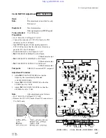
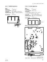
3-7-2. TX PROMPT VIDEO BPF Adjustment
Rank
:
C
Note
:
Make sure that “3-7-1. TX PROMPT
VIDEO Demodulation Adjustment”
is done.
When adjusting this step, the length of
triaxial cable is required less than 500 m.
Equipment
:
Oscilloscope, Video signal generator
To be extended
:
DM-94 board
Preparation
• S4 (CCU
→
CAM/CAM
→
CCU)/
MD-83 board (BVP side)
→
“CCU
→
CAM”
• Connect the harness of MPX filter to CN35 (PROMPT)
connector on DM-97 board (BVP side).
• Feed the 10 STEP signal from the video signal generator
to PROMPTER connector (CCU rear panel).
• S5 (TX
←
→
RX)/
DM-94 board (CCU-700A/700AP)
→
“TX”
• S6 (TX
←
→
RX)/
DM-94 board (CCU-700A/700AP)
→
“TX”
• S1 (MODE AUTO/MAN)/
DM-94 board (CCU-700A/700AP)
→
“MAN”
• S2 (CABLE LENGTH)/
DM-94 board (CCU-700A/700AP)
→
“1”
Test point
:
Board suffix-12 only
Center pin of S6 switch (GND:
E13)/DM-94 board
Board suffix-13 and higher
TP22 (GND: E13)/DM-94 board
Adjusting point
:
1
CV2 (PROMPT TX FREQ 1)/
DM-94 board
1
CV3 (PROMPT TX FREQ 2)/
DM-94 board
Adjustment Procedure
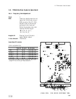
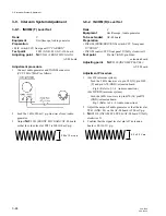
• Adjust
1
CV2 and
1
CV3 alternately so that the level
“A” is maximum.
Note
: After the adjustment, set as follows.
• S1 (MODE AUTO/MAN)/
DM-94 board (CCU-700A/700AP)
→
“AUTO”
• S2 (CABLE LENGTH)/
DM-94 board (CCU-700A/700AP)
→
“0”
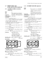
3-7. PROMPT VIDEO Cable
Compensation System Adjustment
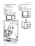
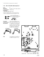
3-7-1. TX PROMPT VIDEO Demodulation
Adjustment
Rank
:
B
Note
:
When adjusting this step, the length of
triaxial cable is required less than 500 m.
Equipment
:
Oscilloscope, Video signal generator
To be extended
:
DM-94 board
Preparation
• S4 (CCU
→
CAM/CAM
→
CCU)/
MD-83 board (BVP side)
→
“CCU
→
CAM”
• Connect the harness of MPX filter to CN35 (PROMPT)
connector on DM-97 board (BVP side).
• Feed the 10 STEP signal from the video signal generator
to PROMPTER connector (CCU rear panel).
• S5 (TX
←
→
RX)/
DM-94 board (CCU-700A/700AP)
→
“TX”
• S6 (TX
←
→
RX)/
DM-94 board (CCU-700A/700AP)
→
“TX”
• S1 (MODE AUTO/MAN)/
DM-94 board (CCU-700A/700AP)
→
“MAN”
• S2 (CABLE LENGTH)/
DM-94 board (CCU-700A/700AP)
→
“1”
Test point
:
Board suffix-12 only
Center pin of S6 switch
(GND: E13)/DM-94 board
Board suffix-13 and higher
TP22 (GND: E13)/DM-94 board
Adjusting point
:
1
RV21 (PROMPT TX DEV)/
DM-94 board
Specification
:
A = 25
±
3 %
Adjustment Procedure
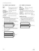
• Adjust
1
RV21 so that the level “A” is 25
±
3% when the level
“B” is 100% with using VAR control of the oscilloscope.
Note
: After the adjustment, set as follows.
• S1 (MODE AUTO/MAN)/
DM-94 board (CCU-700A/700AP)
→
“AUTO”
• S2 (CABLE LENGTH)/
DM-94 board (CCU-700A/700AP)
→
“0”
A
A=25 3%
+
_
B=100%
3-7. PROMPT VIDEO Cable Compensation System Adjustment

