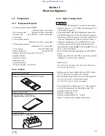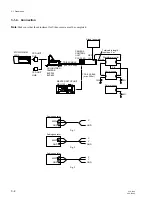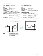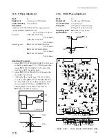
3-3
CCU-700A
CCU-700AP
3-1-5. Initial Setting
1. Initial setting of each switch
CCU-700/700P
[VA-156 board]
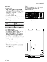
S1 (Y SEL CAM/AUX)
Marked side
S125 (R-Y SEL CAM/AUX)
Marked side
S126 (TEST ON/OFF)
“ON” *1
S221 (B-Y SEL CAM/AUX)
Marked side
S1892 (V BLKG); NTSC ONLY
“20H”
S1962 (REMOTE REM/LOCAL)
“LOCAL” *2
S2032 (CB SELECT) [For UC]
“SMPTE” *3
[For EK]
“EBU”*3
[DM-94 board]
S1 (MODE AUTO/MANU)
“AUTO”
S3 (Y 2nd AGC)
“ON”
S4 (C 2nd AGC)
“ON”
[AT-88 board]
S201 (MIC 1 GAIN 0dB/–20dB)
“0dB”
S301 (MIC 2 GAIN 0dB/–20dB)
“0dB”
S1006 (REMOTE MODE 1 CMD/ISR)
“CMD”
S1007 (REMOTE MODE 2 CMD/ISR)
“CMD”
S2061 (INPUT SELECT 1CH/2CH)
“2CH”
S2081 (PGM GAIN 0dB/–20dB)
“0dB”
S2082 (PGM MIX ON/OFF)
“OFF”
S2341 (INCOM MIX ON/OFF)
“ON”
*1: When finishing the adjustment, set S126 (TEST ON/
OFF)/VA-156 board to “OFF”.
*2: S1962 is set to “REMOTE” at the factory.
*3: When finishing the adjustment, set S2032 (CB SE-
LECT)/VA-156 board to your desired position.
MSU-700
•
POWER AND SIGNAL SWITCH BLOCK
ALL button
“OFF (lamp goes off)”
CAM PW button
“ON (light up)”
TEST 1 button
“OFF (lamp goes off)”
TEST 2 button
“OFF (lamp goes off)”
BARS button
“OFF (lamp goes off)”
CLOSE button
“ON (light up)”
•
CAMERA HEAD/CCU CIRCUIT ON/OFF BLOCK
DETAIL OFF button
“OFF (light up)”
KNEE OFF button
“OFF (light up)”
AUTO KNEE button
“OFF (lamp goes off)”
MATRIX OFF button
“OFF (light up)”
•
AUTO SETUP BLOCK
LEVEL button
“OFF (lamp goes off)”
WHITE button
“OFF (lamp goes off)”
BLACK button
“OFF (lamp goes off)”
•
OTHERS
GAMMA OFF button
“ON (lamp goes off)”
MASTER GAIN select button
“0”
2. Presetting of compensation signal
• Preset (center value) all compensation signals output
from the microcessor before starting the adjustment. If
not, the adjustments will not be set correctly even if the
specifications are met.
• How to preset the compensation data.
1
Turn off the power of CCU.
2
S1002-8 (CONTROL CLEAR)/AT-88 board
→
“ON”
3
Turn on the power of CCU.
n
• This switch setting is valid only when the CCU
number set with S1001/AT-88 board is 96 or less.
• When the switches 1to 8 of S1001/AT-88 board are all
set to “ON” with S1002-8 set to “ON”, the data of
hour meter stored in microprocessor on the AT-88
board is reset.
• When the switches 2 to 8 of S1001 are set to “ON”
with S1002-8 set to “ON”, the special character signal,
set by a customer, is deleted.
• When finishing the overall adjustment, set S1002-8
(CONTROL CLEAR) /AT-88 board to “OFF”.
3-1. Preparation

