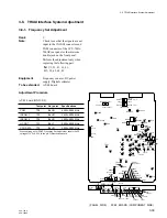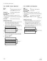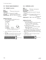
3-52
CCU-700A
CCU-700AP
Less than
20 mV p-p
Less than
20 mV p-p
3-11-2. PROD RTS CANCEL Adjustment
n
• The following adjustment is necessary when the inter-
com is RTS system. Also, this information is only for
repair purpose.
Rank
:
C
Equipment
:
Oscilloscope, Audio generator
To be extended
:
AT-88 board
Preparation
• MIC switch/CCU front panel
→
“CARBON”
• INCOM (PROD/PRIV/ENG) switch/
AT-88 board panel
→
“PROD”
• S2241 (INCOM 2 SELECT)/AT-88 board
→
“RTS”
• Connect pin B70 and pin D70/
extension board with 200
Z
resistor.
Test point
:
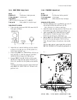
TP43 (GND: E10)/AT-88 board
Adjustment Procedure
1.
Feed the 1 kHz, 220 mV p-p sine-wave to INCOM
connector (CCU-700A/700AP).
2.
Adjust
1
RV2241 (PROD RTS CANCEL)/AT-88
board so that the audio level at TP43 (GND: E10)/AT-
88 board is minimum.
3-11. RTS Intercom System Adjustment
3-11-1. ENG RTS CANCEL Adjustment
n
• The following adjustment is necessary when the inter-
com is RTS system. Also, this information is only for
repair purpose.
Rank
:
C
Equipment
:
Oscilloscope, Audio generator
To be extended
:
AT-88 board
Preparation
• MIC switch/CCU front panel
→
“CARBON”
• INCOM (PROD/PRIV/ENG) switch/
AT-88 board panel
→
“ENG”
• S2491 (INCOM 1 SELECT)/AT-88 board
→
“RTS”
• Connect between pin D71 and pin B72/extension board
with 200
Z
resistor.
Test point
:
TP46 (GND: E11)/AT-88 board
Adjustment Procedure
1.
Feed the 1 kHz, 220 mV p-p sine-wave to INCOM
connector (CCU-700A/700AP).
2.
Adjust
1
RV2491 (ENG RTS CANCEL)/AT-88 board
so that the audio level at TP46 (GND: E11)/AT-88
board is minimum.
3-11. RTS Intercom System System Adjustment
TP45
TP44
E1
TP42
E11
TP46
S2491
ENG SELECT
S1004
S1003
S1005
S2301 S2062
TP43
TP40
E10
RV2342
RV2341
RV2451
RV2452
RV2491
RV2211
RV2212
RV2241
S2241
PROD SELECT
-
12
-
5
+5
+12
NORM
MIN
CH
-
1
NORM
MIN
CH
-
2 CLEAR
MIC LEVEL
CCU PAINT
REAR
INCOM MIC
DYNAMIC
CARBON
ENG
PRIVATE
PROD
PGM
MIX
INCOM
SELECT
SIDE
TONE
2W
LEVEL
2W
CANCEL
RTS
CANCEL
2W
LEVEL
2W
CANCEL
RTS
CANCEL
ENG
PROD
AT
(PANEL SIDE) AT-88 BOARD (COMPONENT SIDE)
TP3


