1-15
CCU-700A(UC)
CCU-700AP(CE)
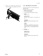
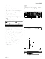
DM-94 board
• S1 (AUTO/MANU)
When this switch is set to “AUTO”, a triaxial cable
length between the CCU and camera head is detected on
automatic. When set to “MANU” (MANUAL), the cable
length can be set on manual using the switch S2 (CA-
BLE LENGTH SELECT).
Factory-setting is “AUTO”.
• S2 (CABLE LENGTH SELECT)
This switch is valid with the switch S1 (AUTO/MANU)
set to “MANU”. Set the switch according to the follow-
ing table.
Factory-setting is “0” (100 m).
Switch
Cable length
Switch
Cable length
setting
setting
0
100 m
3
640 m
1
280 m
4
820 m
2
460 m
5
1000 m
• S3 (Y-ch 2nd AGC ON/OFF)
• S4 (CHROMA-ch 2nd AGC ON/OFF)
Used for the RF AGC adjustment. Normally set to “ON”.
• S5 (PROMPTER POWER SELECT TX/RX)
When this switch is set to “TX”, a power is supplied to
the modulation circuit sending a prompter signal. When
set to “RX”, power is supplied to the demodulation
circuit receiving a prompter signal from the camera head.
Be sure to set this switch and S6 (PROMPTER RF
SELECT) switch to the same mode.
Factory-setting is “TX”.
• S6 (PROMPTER RF SELECT TX/RX)
When this switch is set to “TX”, a circuit sending an RF
signal activates, and when set to “RX”, a circuit receiv-
ing an RF signal activates. Be sure to set this switch and
S5 (PROMPTER POWER SELECT) to the same mode.
Factory-setting is “TX”.
-
12
-
5
+5
+12
DM
TX
RX
S5
ON
S4
S1
S2
Y GND
Y
B
-
Y
R
-
Y
R
-
Y
B
-
Y
ON
S3
Y AGC COUNT
S6
TX
RX
MAN
AUTO
CABLE
LENGTH
1-4. Function of Internal Switch
n
When the switches S5 and S6 are set to “RX”, a prompter
signal from the camera head is output to spare
connector as shown below.
(Rear panel)
CAMERA
MIC OUTPUT
ANALOG INPUT
RTS
INTERCOM/TALLY/PGM
REMOTE
ANALOG OUTPUT
DIGITAL VIDEO
COAX
REMOTE
Spare connector

