2-3
CCU-700A(CU)
CCU-700AP(CE)
2-1-6. Replacement of Power Unit
1.
Disconnect the power cord from the CCU-700A/
700AP rear panel. Remove the front panel.
2.
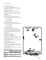
Loosen the screw (+PWH3
x
15) and remove the blind
plate. Loosen the four screws (+PWH4
x
10) fixing the
power unit while pushing the power unit forward at the
fan in the rear of the unit.
n
• Support this unit by both hands in extracting because
it is so heavy.
• The four screws fixing the power unit cannot be
removed from the power unit, because stoppers are
provided for them.
3.
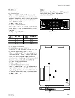
Set the two voltage selectors on the rear and side
panels, of a replacement power unit as illustrated.
MAIN CAMERA
MAIN CAMERA
Label
MAIN fuse
2A 125V (NTSC)
T2AH 250V (PAL)
CAMERA fuse
6.3A 125V (NTSC)
T3.15AH 250V (PAL)
4.
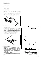
Remove the blind plate of the replacement power unit,
then remove and discard the two fuses in the unit. Put
the supplied fuses into each fuse holder as the label
indicates.
5.
After the fuses are replaced, install the power unit and
tighten the four screws (+PWH4
x
10). Return the blind
plate.
6.
After the replacement is complete, connect to the
power cord and turn on the power of CCU and check
that the power supplies are correct.
2-1. Replacement of Main Parts
110-120V
220-240V
CCU-700
[Rear]
100V
115V
[Side]
110-120V
220-240V
CCU-700P
100V
115V
+PWH 4x10
+PWH3x15
Blind plate
+PWH4x10
Power unit
+PWH 4x10


