3-19
CCU-700A
CCU-700AP
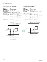
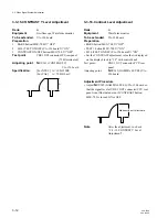
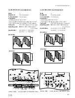
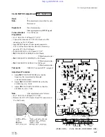
3-3-28. R Level Adjustment
Rank
:
A
Equipment
:
Waveform monitor
To be extended
:
VA-156 board
Preparation
• BARS button/MSU-700
→
“ON”
Test point
:
WF 2 OUT connector/CCU rear panel
Adjustment Procedure
1.
WAVEFORM MONITOR button/MSU-700
→
“R”
2.
Adjusting point:
1
RV135 (R MATRIX BAL)/
VA-156 board
Specification:
[For NTSC] A = B = 0
+1
IRE
–0
[For PAL]
A = B = 0
+7
mV
–0
3.
Adjust
1
RV136 (R WF LEVEL)/VA-156 board so
that the level “b” is equal even if WAVEFORM
MONITOR button/MSU-700 is set to “R” or “G”.
Specification:
Level difference =
[For NTSC] 0
±
1 IRE
[For PAL]
0
±
7 mV
Note
: After the adjustment, set as follows.
• WAVWFORM MONITOR button/MSU-700
→
“ENC”
[For NTSC]
[For PAL]
A
A
3-3. Video Signal System Adjustment
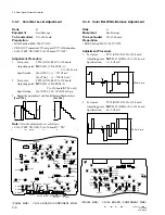
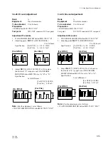
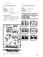
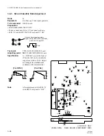
3-3-29. B Level Adjustment
Rank
:
A
Equipment
:
Waveform monitor
To be extended
:
VA-156 board
Preparation
• BARS button/MSU-700
→
“ON”
Test point:
WF 2 OUT connector/CCU rear panel
Adjustment Procedure
1.
WAVEFORM MONITOR button/MSU-700
→
“B”
2.
Adjusting point:
1
RV270 (B MATRIX BAL)/
VA-156 board
Specification:
[For NTSC] A = B = 0
+1
IRE
–0
[For PAL]
A = B = 0
+7
mV
–0
3.
Adjust
1
RV271 (B WF LEVEL)/VA-156 board so
that the level “b” is equal even if WAVEFORM
MONITOR button/MSU-700 is set to “B” or “G”.
Specification:
Level difference =
[For NTSC] 0
±
1 IRE
[For PAL]
0
±
7 mV
Note
: After the adjustment, set as follows.
• WAVWFORM MONITOR button/MSU-700
→
“ENC”
B
B
[For NTSC]
[For PAL]
A
A
[For NTSC]
[For PAL]
[For NTSC]
[For PAL]
B
B


