3-18
BVP-500
BVP-500P
3-2. Self-Diagnosis
The BVP-500/500P has a diagnosis mode used for self-diagnosis of every plug-in board and the OHB.
The diagnosis page is displayed on the viewfinder screen.
•
Operation
Select “Diagnosis” page of the Operation menu referring to Section 3-1.
•
Viewfinder Screen
•
Display Descriptions
Marks
Board/Block
Judging Point
Expected Abnormality
1
OHB(CCD UNIT) Communication with IC18, IC19/TG-159
Communication error
2
PR-211
Communication with IC49
Communication error
3
VA-163
Communication with IC26
Communication error
4
AT-95
Communication with IC46
Communication error
5
SG-234
Communication with IC21
Communication error
6
DA-88
Communication with IC10
Communication error
7
IF-538
Communication with IC603
Communication error
8
MD-103
Y RF output
• RF carrier levels for Y
Color-difference
and R-Y/B-Y are out of specs.
*
RF output
• Improper connection of the board
9
AU-211
+7.5 V and
• Power voltage for the
INCOM +7.5 V
board is out of specs.
*
• Improper connection of the board
0
TR-90
RF output (TP3)
• Carrier level for AUDIO
RF is out of specs.
*
• Improper connection of the board
* Only when no video signal is input.
n
When the BVP-500/500P is not connected to the CCU, the columns
8
,
9
and
0
will display “– –”.
0
9
8
7
6
5
1
2
3
4
3-2. Self-Diagnosis
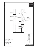
Summary of Contents for BVP-500
Page 14: ...1 6 BVP 500 BVP 500P 1 3 Outside Dimentions 1 3 Outside Dimentions Unit mm ...
Page 22: ...1 14 BVP 500 BVP 500P ...
Page 120: ......