5-7
BVP-500
BVP-500P
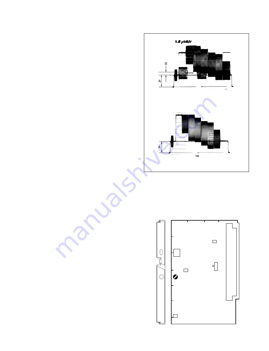
5-4. Monitor Out Adjustment
Equipment
: Waveform monitor
Test Point
: MONITOR connector
Preparations:
• Connect the waveform monitor to the MONITOR
connector.
• S650 (MONITOR SELECT)/IF-538 panel
→
VBS
Adjustment Procedures:
1.
Set the DISPLAY switch/rear panel to MENU while
pushing up the MENU SELECT switch to ENTER.
2.
Set the menu as follows.
MENU
: System config
PAGE
: Y/Chroma (S2)
ITEM
: CB
→
On
3.
Adjustment Point
:
1
RV100 (VIDEO LEVEL)/
IF-538 panel
Specifications
: A = 40
±
1 IRE (for NTSC)
A = 300
±
2 mV (for PAL)
4.
Adjust the test setup. (NTSC only)
Adjustment Point
:
MENU
: System config
PAGE
: Y/Chroma (S2)
ITEM
: TEST SETUP
Specifications
: B = 7.5
±
1 IRE
File Store:
Execute the file store. Throw the MENU SELECT
switch to ENTER to execute.
MENU
: Triming File
PAGE
: Triming File (T1)
ITEM
: File Store
5-4. Monitor Out Adjustment
4
3
2
1
A
B
C
D
E
F
G
IF
VBS
RET
VF
VIDEO
LEVEL
TP870
S650
TP820
S200
RV100
E10
IF-538 BOARD (A SIDE)
(For NTSC)
(For PAL)
Summary of Contents for BVP-500
Page 14: ...1 6 BVP 500 BVP 500P 1 3 Outside Dimentions 1 3 Outside Dimentions Unit mm ...
Page 22: ...1 14 BVP 500 BVP 500P ...
Page 120: ......


