55
STARTING PROCEDURE
________________________________________________________________________________________
2. Disconnect all terminals at the bottom side of the control module
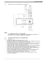
3. Dismantle the front cover of the control module by removing 4 screws on top side of the control module
and 4 screws at the bottom of the control module.
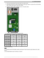
4. Identify dip switches S401 and S402 as shown in the picture below:
5. Set the dip switches according to the below table:
Dip Switch No.
4-20 mA*
0-20 mA
0-10VDC
Dip-Sw. S401A
On
On
Off
Dip-Sw. S401B
On
On
Off
Dip-Sw. S401C
Off
Off
On
Dip-Sw. S401D
Off
Off
On
Dip-Sw.
S402A
On Off Off
Dip-Sw. S402B
No use
No use
No use
* Factory default setting
Notes:
x
It is important that the RVS-DXM is properly grounded and control module is tightly fastened to the power
section.
x
Use twisted shielded cable for thermistor connection.


