54
STARTING PROCEDURE
_____________________________________________________________________________________
8.
STARTING PROCEDURE
Note:
It is necessary to connect a motor to load terminals otherwise S.SCR or WRONG CONNECTION Protection is
activated. Other loads such as light bulbs, resistors, etc. may also cause WRONG CONNECTION Fault.
1
When mains voltage is connected to the RVS-DXM, even if control
voltage is disconnected, full voltage may appear on the starter load
terminals. Therefore, for isolation purposes, it is necessary to connect an
isolating device before (upstream) the starter.
2
Power factor correction capacitors or overvoltage protection devices must
not be installed on starters load side. When required, install it
RQVWDUWHU¶V
line side.
3
:KHQXVLQJ³,QVLGHGHOWD´FRQQHFWLRQZURQJFRQQHFWLRQRIWKHVWDUWHURU
the motor, will seriously damage the motor; therefore make sure motor is
connected properly!
4
Do not interchange line and load connections
5
Before starting the motor verify its rotation direction. If needed,
disconnect the rotor from the mechanical load and verify the right rotation
direction.
6
Prior to Start up procedure make sure that line voltage and control
vo
OWDJHPDWFKWKHRQHVVKRZQRQWKHVWDUWHU¶VQDPHSODWH
7
When start signal is initiated and a motor is not connected to load
terminals, the SHORT SCR or WRONG CONNECTION protection will be
activated.
8.1
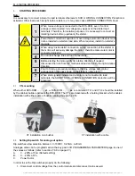
CTs mounting
When either RVS-DXM
ÂÂÂ
ÂÂÂÂÂÂ
63
Â
or
RVS-DXM
ÂÂÂ
ÂÂÂÂÂÂ
66
Â
are ordered CTL1 and CTL3 should be installed
by the cabinet builder upstream the RVS-DXM. The CTs are delivered with a holding bracket which enables
installation with either cable or busbar running through the CTs:
CT installation on a busbar
CT installation with a cable
8.2
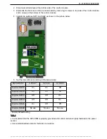
Setting Dip switch for analog-out option
Dip switches allow selection between: 0-10VDC, 0-20mA, 4-20mA
Analogue value can be programmed via the key pad in I/O PROGRAMMING PARAMETERS page to one of
the values as follows: (refer to section 7.6.9 on page 47.)
A.
«RI)/$'HIDXOWVHWWLQJ
B.
«RI3Q
C. Power
factor
In order to set the Dip switches properly do the following:
1. Disconnect
control
voltage from the control module and disconnect mains as well.


